- 662 -
4.1.5 Mapping for IEC 61850 communication
The user can operate the SPOS function over IEC 61850 communications† following mapping
using GR-TIEMS. Note that the SPOS function is designed for the class of “Single Point
Controller (SPC)” in the IEC 61850 standard for communication. The user should follow these
steps, each of which is discussed below,
Step1: Editing Logical Node
Step2: Mapping output data
Step3: Mapping input data
(i) Editing Logical Node
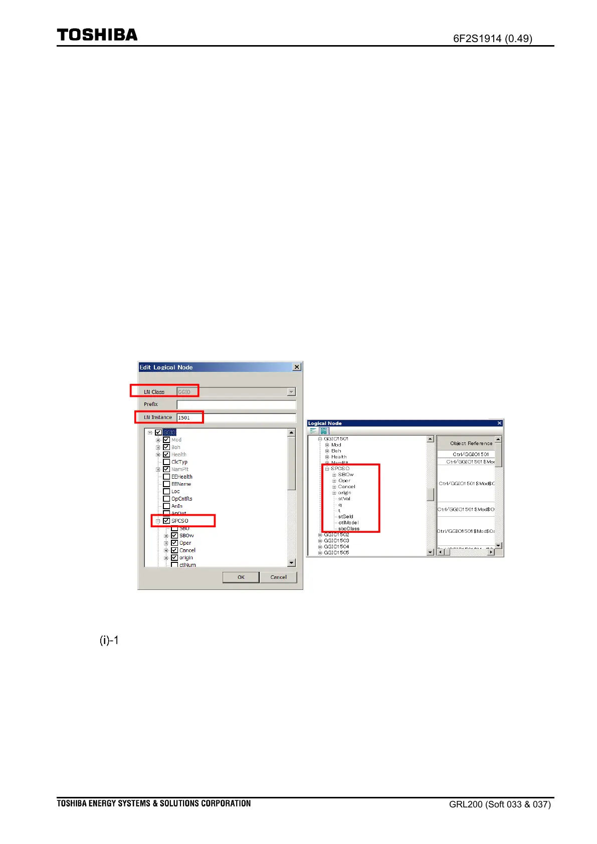
The user will need to create a logical node (LN) for the SPOS01 function. Figure 4.1-40
exemplifies the editing of a LN; the LN “General Input/output (GGIO)” is chosen for the
SPOS01 function. After the user has defined an object “SPCSO”, the SPOS01 logical node can
be available with the name “GGIO” plus “LN Instance”. Create a definition of the object
“SPCSO” in the SPOS01 logical node. Either the SBO mode or the DIR mode can be chosen in
the editing for the LN.
Figure 4.1-40 Defining “SPCSO” object in GGIO1501 logic node
Defining SBO mode
Figure 4.1-41 exemplifies the SPOS01 logic node saved as “GGIO1501”. In the SBO mode, the
user should select the following items for the “GGIO1501$SPCSO” using GR-TIEMS:

 Loading...


