- 704 -
4.2.6(i)-3)
7
Note: A supervision of the Binary IO module can detect connection errors for BI circuits
.
8
Note: The “Common control” (CMNCTRL) function can test and check the operation-
direction of logic. When the user sets Off for scheme switch [SCDEN], operation of
the logic is blocked if the logic is running in the same operation-direction
compared with the previous operation-direction. Alternatively, if On is set for the
scheme switch, the logic is not blocked.
9
Note: The user must program the PLC logic for “Control hierarchy condition”. The user
must connect the “Control hierarchy condition” to the select condition logic using
the connection point “DPSY01IN_TMP_28”. For more information, see Chapter
Control and monitoring application: Control hierarchy
. See PLC#3 of Table 4.2-8.
Note that the logic outputs are generated separately for both the Closing-
execution and the Open-execution.
(viii) Signal name and number
Note: The user should note the meaning of the following abbreviations shown in column
“M/O” of each table:
“O” signifies that the signal is provided for optional use.
“M” signifies that the user should map/set/configure the signal; otherwise, the
user may experience an operational failure if the default settings are
used.
“N/A” signifies that the user cannot change the state of the signal.
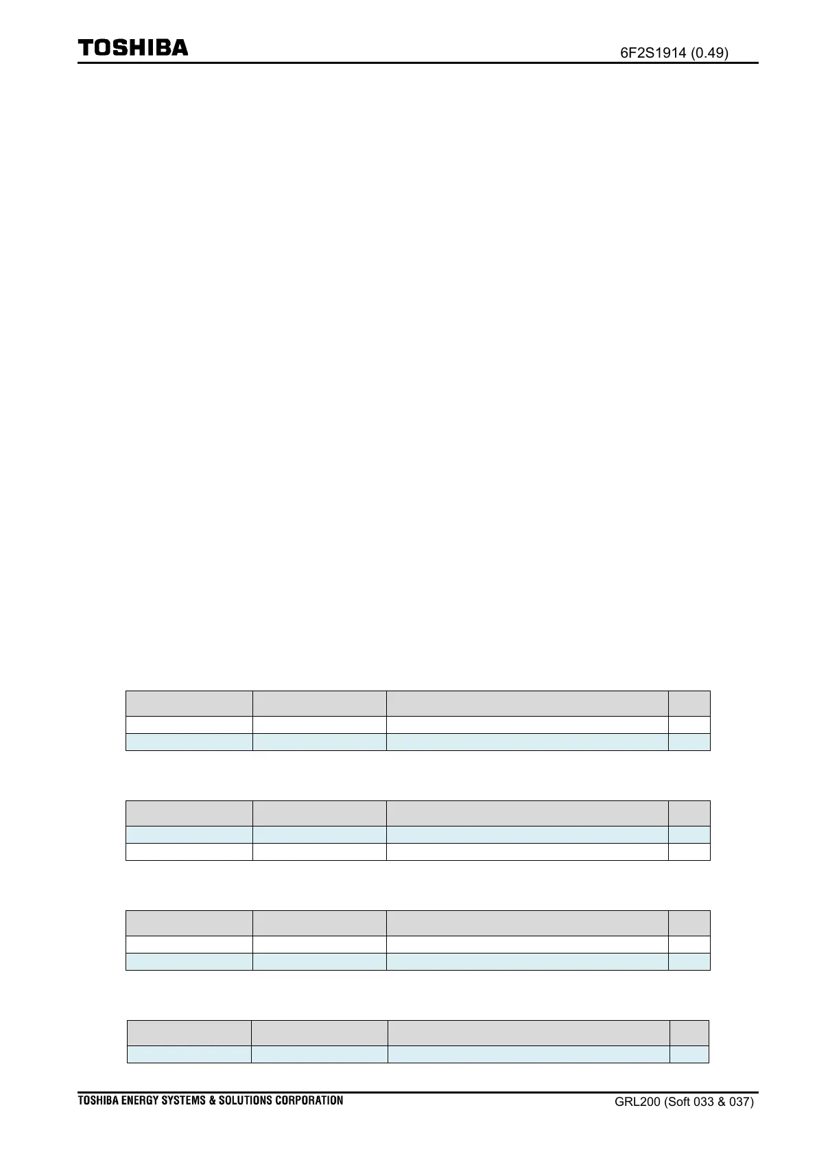
Table 4.2-15 PLC connection points (Input point for PLC#1 user a configurable condition)
DPSY01 user configurable condition(PLC#1)
DPSY02 user configurable condition(PLC#1)
Table 4.2-16 PLC connection points (Input point for PLC#2 operate command Closing)
DPSY01 user configurable condition(PLC#2)
DPSY02 user configurable condition(PLC#2)
Table 4.2-17 PLC connection points (Input point for PLC#3 operate command Closing)
DPSY01 user configurable condition(PLC#3)
DPSY02 user configurable condition(PLC#3)
Table 4.2-18 PLC connection points (Input point for operate condition logic)
DPSY01 user additional condition(PLC#1)

 Loading...


