Layer 2,3,IPv6+QoS Switch
_____________________________________________________________________________
Layer 2,3,IPv6+QoS Network Switch User Manual Version 0.1 Page: 34/970
‧ ARP support
‧ IP Routing support
‧ OSPF v2 and v3 support
‧ RIP v1 and v2 support
‧ Router Discovery Protocol support
‧ VLAN routing support
‧ Virtual Router Redundancy Protocol (VRRP) support
‧ IP Multicast support
‧ Protocol Independent Multicast - Dense Mode (PIM-DM) support
‧ Protocol Independent Multicast - Sparse Mode (PIM-SM) support
‧ IGMP v1, v2, and v3 support
‧ DVMRP support
‧ IPV6 function
Supports DHCPv6 protocol, OSPFv3 protocol, Tnneling, loopback
Provides to configure IPv6 rotuing interface, routing preference
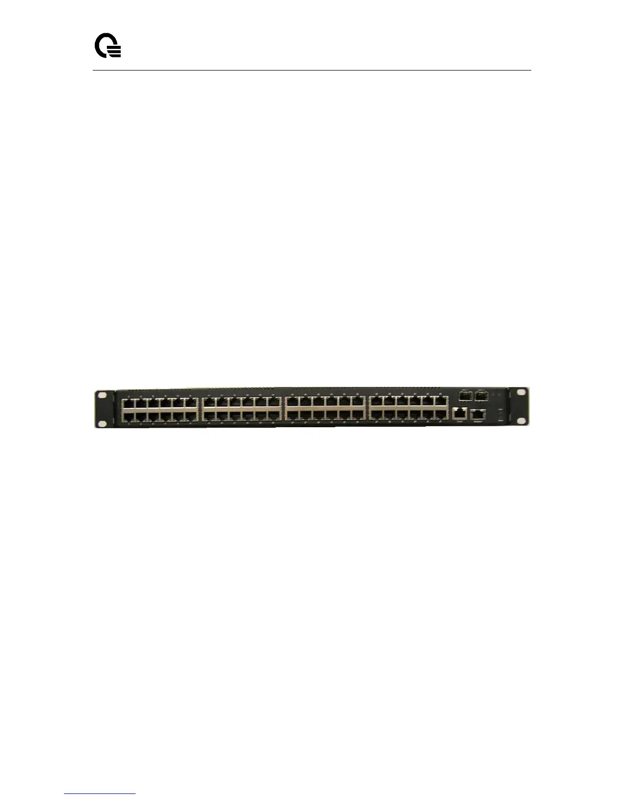
1.3 Front-Panel Components
The front panel of the Switch consists of 48 1-Giga interfaces, 4 LED indicators, one
built-in 1000/100/10 RJ-45 Ethernet service ports, an RS-232 communication port.
The upper LED indicators display power situation. The lower LED indicators displays the
status of the switch. Two LED indicators display the status of SFP+ interface, An RS-232 DCE
console port is for setting up and managing the Switch via a connection to a console terminal or
PC using a terminal emulation program.
1.4 LED Indicators
The Status LED indicator represnts status of the switch. The Power LED indicator
represent power ON or OFF.
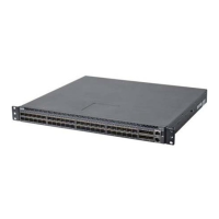
1.5 Rear Panel Description
The rear panel of the Switch contains an redundant AC/DC power unit and three fans.