8400 HighLine | Parameter setting & configuration
Commissioning
Commissioning the "Table positioning" TA using the »Engineer«
50 L Firmware ≤ 05.00 - DMS 4.2 EN - 02/2010
3.6 Commissioning the "Table positioning" TA using the »Engineer«
System constellation
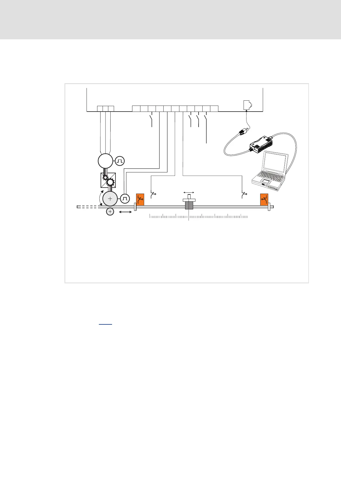
[3-3] Block diagram for wiring the commissioning example for the "Table positioning" application
1. Prepare drive controller for commissioning
Inhibit drive controller: Set X5/RFR terminal to LOW level or open contact (see block
diagram [3-3]
for wiring)
Ensure that the mains voltage and the motor cables are wired correctly.
– Check for correct wiring of the supply feeder and the motor cable, even if motor
operation during commissioning is not intended at first.
Connect USB diagnostic adapter.
Connections:
• X5/RFR: Controller enable
•X5/DI1: Encoder, track A
•X5/DI2: Encoder, track B
• X5/DI3: Left hardware limit switch
• X5/DI4: Right hardware limit switch
• X5/DI5: "PosExecute" function
• X5/DI6, X5/DI7: Operating mode setting (following mode, referencing, manual jog, positioning)
• X6: Diagnostic interface for communication between PC and drive controller
V
U
W
X5
GIDI7
DI6
DI5
DI4
DI3
DI2DI1
RFR
24I24E
M
3~
0-Position
20 3010-10-20-30
40
+-
i
A B
PosExecute
RFR
PosProfile
p d
8400 HighLine
X6
X61
X6
DIAG
efesotomasyon.com - Lenze
 Loading...