Firmware ≤ 05.00 - DMS 4.2 EN - 02/2010 L 43
8400 HighLine | Parameter setting & configuration
Commissioning
Commissioning the "Actuating drive speed" TA using the keypad
3.4 Commissioning the "Actuating drive speed" TA using the keypad
System constellation
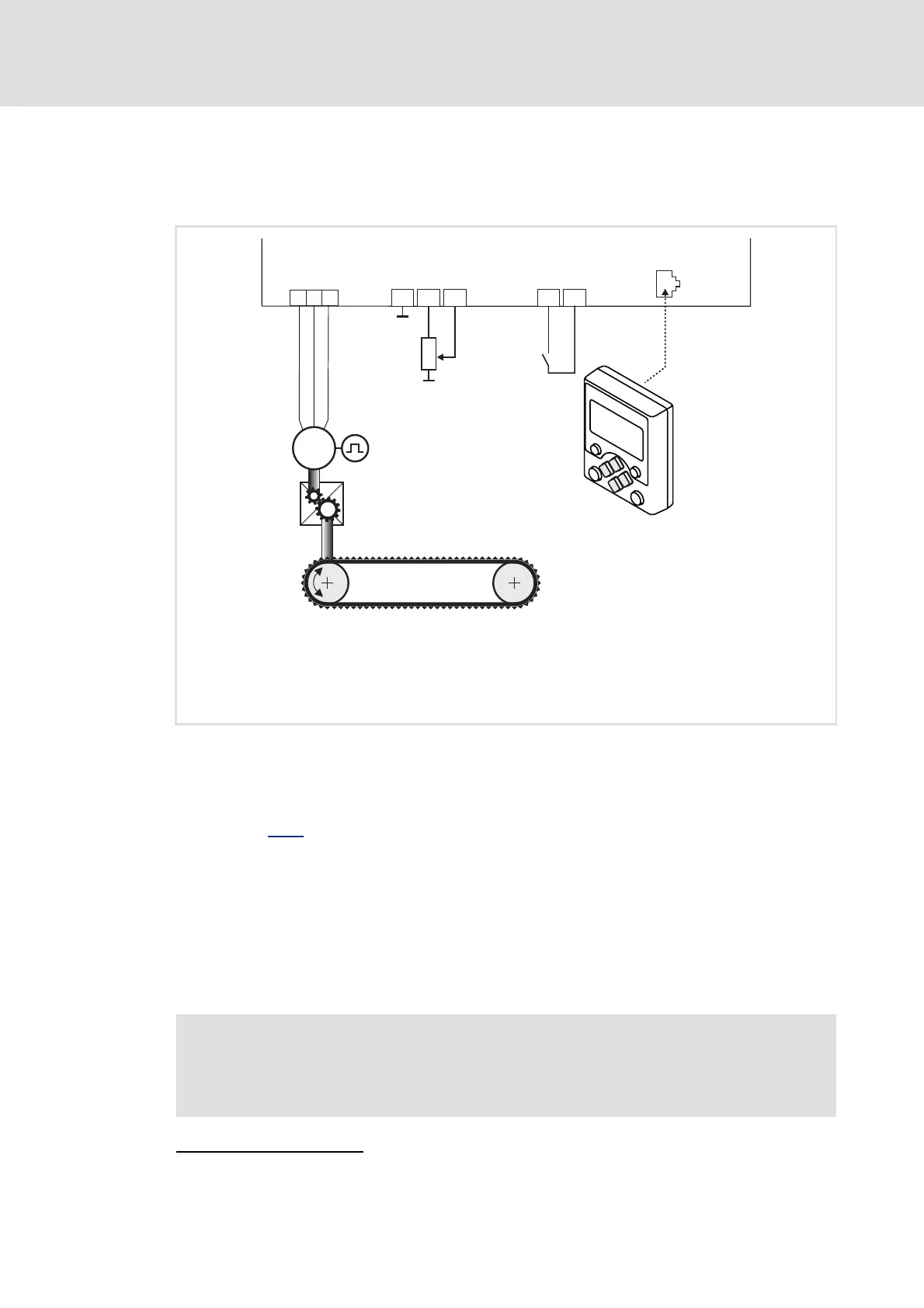
[3-1] Block diagram for wiring the commissioning example for the "Actuating drive speed" application
1. Prepare the keypad and the controller for commissioning
Inhibit drive controller: Set X5/RFR terminal to LOW level or open contact (see block
diagram [3-1]
for wiring).
Ensure that the mains voltage and the motor cables are wired correctly.
– Check for correct wiring of the supply feeder and the motor cable, even if motor
operation during commissioning is not intended at first.
Plug the keypad onto the controller (diagnostic interface X6).
2. Switch on device
Without motor operation
: Connect the external 24 V supply to X5/24E. Switch on external
supply.
Connections:
• X3/GA: Ground potential (GND) for analogue signals
• X3/AR: Reference voltage (10 V) for analogue signals
• X3/A1U: Input 1 for analogue signals (slider of the setpoint potentiometer R)
• X5/RFR: Controller enable (CINH)
• X6: Slot for keypad/diagnostic interface
V
U
W
X3
X5
X6
RFR24I
A1U
ARGA
M
3~
i
RFR
R
DIAG
8400 HighLine
Stop!
Before stipulating a speed setpoint, check whether the brake in the form of a
holding brake on the motor shaft has been released!
efesotomasyon.com - Lenze
 Loading...