Layer 2,3,IPv6+QoS Switch
_____________________________________________________________________________
Layer 2,3,IPv6+QoS Network Switch User Manual Version 0.1 Page: 683/970
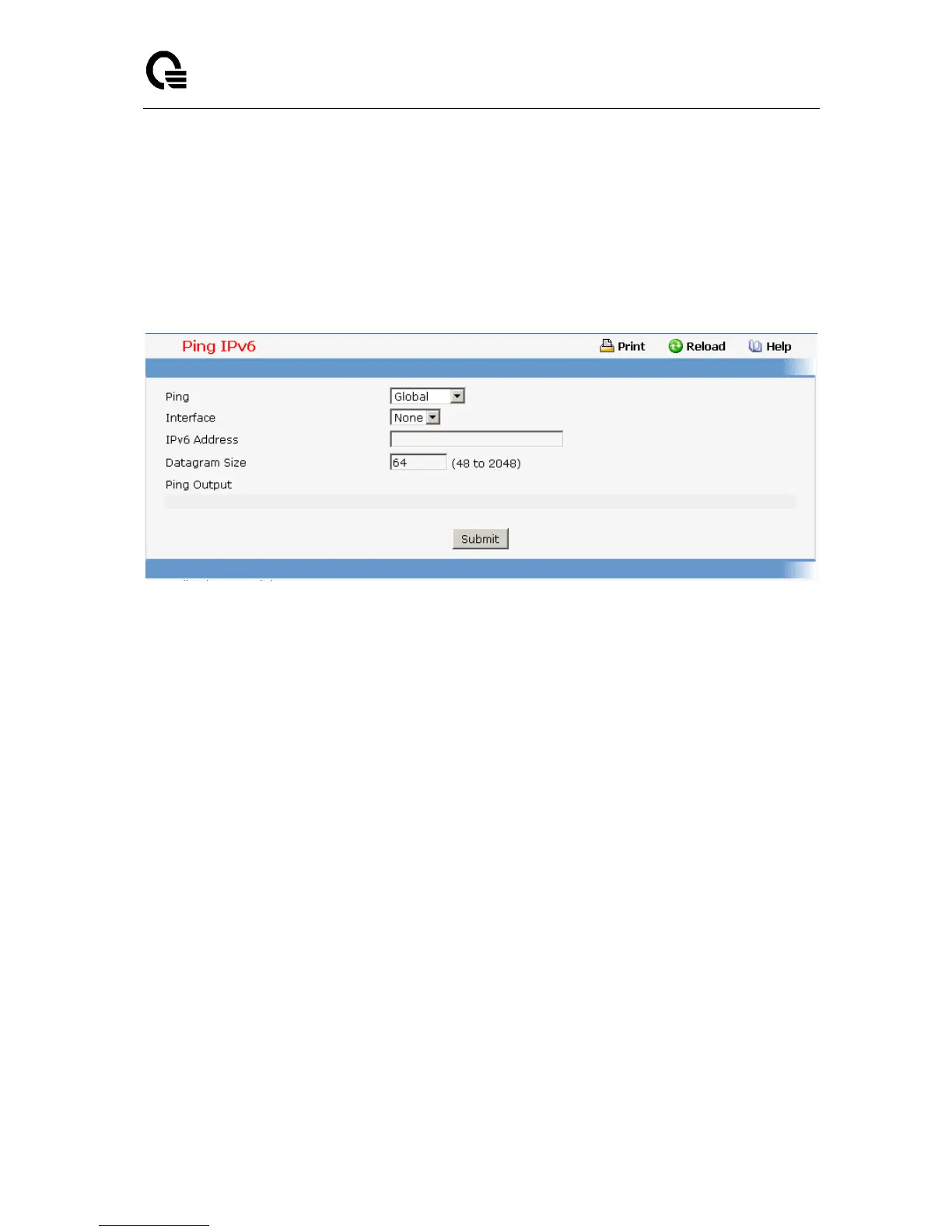
Datagram Size - Enter the datagram size. The valid range is L7_IP6_PING_MIN to
L7_IP6_PING_MAX.
None Configurable Data
Ping Output– The reply result received from switch.
Command Buttons
Submit - This will initiate the ping.
11.2.1.9.12. TraceRoute Function
Use this screen to tell the switch to send a TraceRoute request to a specified IP address.You
can use this to discover the paths packets take to a remote destination. Once you click the
Submit button, the switch will send traceroute and the results will be displayed below the
configurable data. If a reply to the traceroute is you will see 1 x.y.z.w 9869 usec 9775 usec
10584 usec
2 0.0.0.0 0 usec * 0 usec * 0 usec *
3 0.0.0.0 0 usec * 0 usec * 0 usec *
Hop Count = w Last TTL = z Test attempt = x Test Success = y.
Configurable Data
IP Address - Enter the IP address of the station you want the switch to discover path.
The initial value is blank. The IP Address you enter is not retained across a power cycle.
Probes Per Hop - Enter the number of probes per hop. The initial value is default. The
Probes per Hop you enter is not retained across a power cycle.
MaxTTL - Enter the maximum TTL for the destination. The initial value is default value.
The MaxTTL you enter is not retained across a power cycle.
InitTTL - Enter the initial TTL to be used. The initial value is default value. The InitTTL
you enter is not retained across a power cycle.
MaxFail - Enter the maximum Failures allowed in the session. The initial value is default
value. The MaxFail you enter is not retained across a power cycle.
Interval - Enter the Time between probes in seconds. The initial value is default value.
The Interval you enter is not retained across a power cycle.