Nexus
MPC5566 Microcontroller Reference Manual, Rev. 2
Freescale Semiconductor 25-43
NOTE
The WT bits control program and data trace only if the TM bits in the
development control register 1 (DC1) have not been set to enable program
and data trace, respectively.
25.11.8 Data Trace Control Register (DTC)
The data trace control register controls whether DTM messages are restricted to reads, writes, or both for
a user programmable address range. There are two data trace channels controlled by the DTC for the
Nexus3 module. Each channel can also be programmed to trace data accesses or instruction accesses.
Table 25-32 details the data trace control register fields.
22–20
DTE[2:0]
Data trace end control.
000 Trigger disabled
001 Use watchpoint #0 (IAC1 from Nexus1)
010 Use watchpoint #1 (IAC2 from Nexus1)
011 Use watchpoint #2 (IAC3 from Nexus1)
100 Use watchpoint #3 (IAC4 from Nexus1)
101 Use watchpoint #4 (DAC1 from Nexus1)
110 Use watchpoint #5 (DAC2 from Nexus1)
111 Use watchpoint #6 or #7 (DCNT1 or DCNT2 from Nexus1)
19–0 Reserved
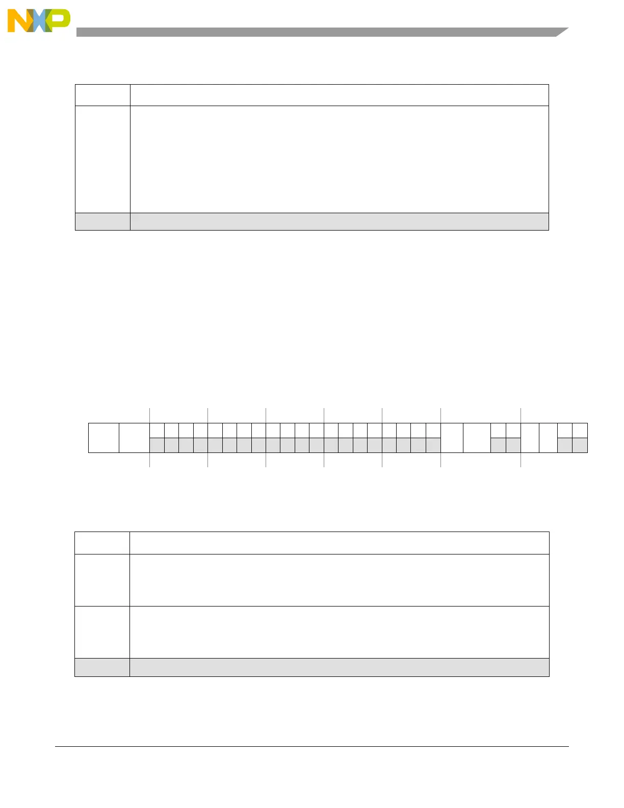
Nexus Reg: 0x000D Access: R/W
31 30 29 28 27 26 25 24 23 22 21 20 19 18 17 16 15 14 13 12 11 10 9 8 7 6 5 4 3 2 1 0
R
RWT1 RWT2
000000000000
RC1 RC2
00
DI1 DI2
00
W
Reset000000000000000000000000 0 0 00 0 0 00
Figure 25-22. Data Trace Control Register (DTC)
Table 25-32. DTC Field Description
Field Description
31–30
RWT1[1:0]
Read/write trace 1.
00 No trace enabled
X1 Enable data read trace
1X Enable data write trace
29–28
RWT2[1:0]
Read/write trace 2.
00 No trace enabled
X1 Enable data read trace
1X Enable data write trace
27–8 Reserved
Table 25-31. WT Field Descriptions (continued)
Field Description

 Loading...


