Nexus
MPC5566 Microcontroller Reference Manual, Rev. 2
Freescale Semiconductor 25-87
25.17.5.1 Data Trace
This section deals with the data trace mechanism supported by the NXDM module. Data trace is
implemented via data write messaging (DWM) and data read messaging (DRM).
25.17.5.2 Data Trace Messaging (DTM)
NXDM data trace messaging is accomplished by snooping the NXDM data bus, and storing the
information for qualifying accesses (based on enabled features and matching target addresses). The
NXDM module traces all data access that meet the selected range and attributes.
NOTE
Data trace is ONLY performed on DMA accesses to the system bus.
25.17.5.3 DTM Message Formats
The NXDM block supports five types of DTM Messages — data write, data read, data write
synchronization, data read synchronization and error messages.
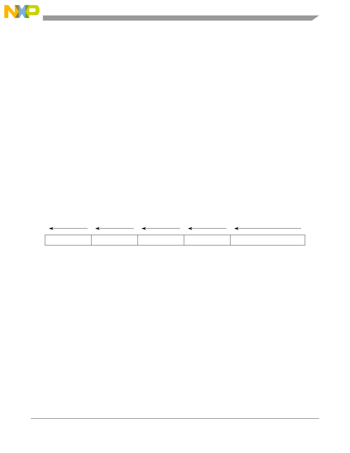
25.17.5.3.1 Data Write and Data Read Messages
The data write and data read messages contain the data write/read value and the address of the write/read
access, relative to the previous data trace message. Data write message and data read message information
is messaged out in the following format:
Figure 25-66. Data Write/Read Message Format
25.17.5.3.2 DTM Overflow Error Messages
An error message occurs when a new message cannot be queued due to the message queue being full. The
FIFO discards incoming messages until it has completely emptied the queue. After it is emptied, an error
message is queued. The error encoding indicates which types of messages attempted to be queued while
the FIFO was being emptied.
If only a data trace message attempts to enter the queue while it is being emptied, the error message
incorporates the data trace only error encoding (00010). If a watchpoint also attempts to be queued while
the FIFO is being emptied, then the error message incorporates error encoding (01000).
DATA
MSB LSB
234
U-ADDR DSZ SRC
5
4 bits
1
TCODE (000101 or 000110)
3 bits1–32 bits1–64 bits 6 bits
Max length = 109 bits; Min length = 15 bits

 Loading...


