Interrupt Controller (INTC)
MPC5566 Microcontroller Reference Manual, Rev. 2
10-6 Freescale Semiconductor
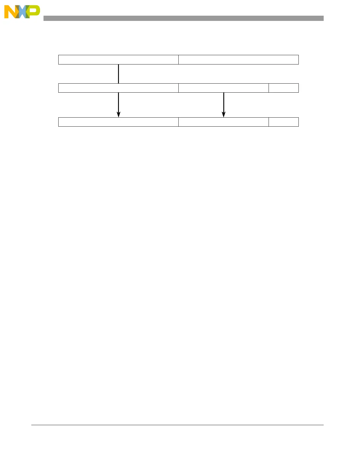
Figure 10-5. Software Vector Mode: Interrupt Exception Handler Address Calculation
Reading the INTC_IACKR acknowledges the INTC’s interrupt request and negates the interrupt request
to the processor. The interrupt request to the processor does not clear if a higher priority interrupt request
arrives. Even in this case, INTVEC does not update to the higher priority request until the lower priority
interrupt request is acknowledged by reading the INTC_IACKR. The reading also pushes the PRI value
in the INTC current priority register (INTC_CPR) onto the LIFO and updates PRI in the INTC_CPR with
the priority of the interrupt request. The INTC_CPR masks any peripheral or software settable interrupt
request at the same or lower priority of the current value of the PRI field in INTC_CPR from generating
an interrupt request to the processor.
The interrupt exception handler must write to the end-of-interrupt register (INTC_EOIR) to complete the
operation. Writing to the INTC_EOIR ends the servicing of the interrupt request. The INTC’s LIFO is
popped into the INTC_CPR's PRI field by writing to the INTC_EOIR, and the size of a write does not
affect the operation of the write. Those values and sizes written to this register neither update the
INTC_EOIR contents nor affect whether the LIFO pops. For possible future compatibility, write four bytes
of all 0s to the INTC_EOIR. The timing relationship between popping the LIFO and disabling recognition
of external input has no restriction. The writes can happen in either order.
However, disabling recognition of the external input before popping the LIFO eases the calculation of the
maximum stack depth at the cost of postponing the servicing of the next interrupt request.
10.1.4.2 Hardware Vector Mode
In hardware vector mode, the interrupt exception handler address is specific to the peripheral or software
settable interrupt source rather than being common to all of them. No IVOR is used. The interrupt
exception handler address is calculated by hardware as shown in Figure 10-6. The upper half of the
interrupt vector prefix register (IVPR) is added to an offset which corresponds to the peripheral or software
interrupt source which caused the interrupt request. The offset matches the value in the Interrupt Vector
field, INTC_IACKR[INTVEC]. Each interrupt exception handler address is aligned on a four-word
(16-byte) boundary. IVOR4 is not used in this mode, and software does not need to read INTC_IACKR to
get the interrupt vector number.
3116150
IVPR
31282716150
+ IVOR4
31282716150
0x00
0x00
OFFSET
OFFSETPREFIX
0x0000
PREFIX
= Interrupt exception
0x0000
handler address

 Loading...


