Enhanced Modular Input/Output Subsystem (eMIOS)
MPC5566 Microcontroller Reference Manual, Rev. 2
Freescale Semiconductor 17-31
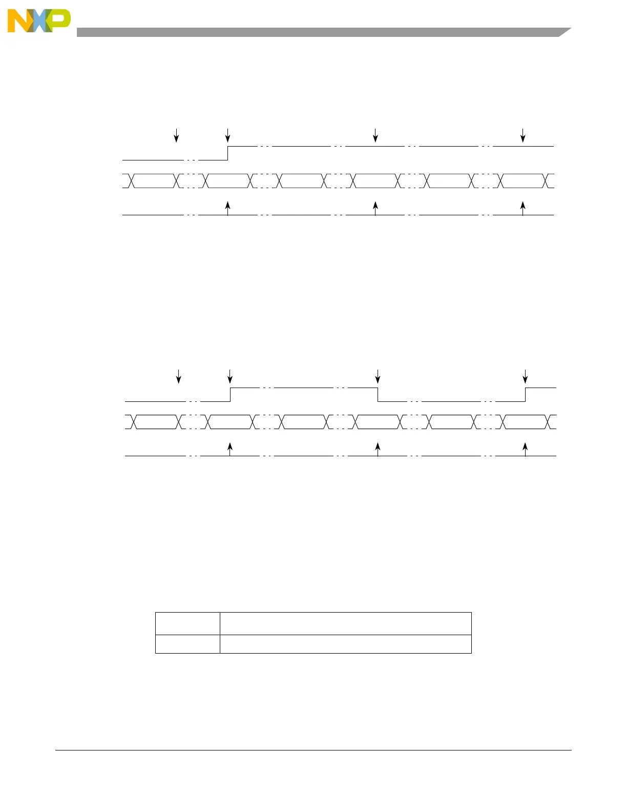
Figure 17-17 shows how to use the unified channel perform a single output compare while transferring
EDPOL to the output flip-flop. This figure toggles the output flip-flop with Figure 17-18 at each match.
Figure 17-17. SAOC Example with EDPOL Value Transferred to the Output Flip-flop
Figure 17-18 shows how to use the unified channel perform a single output compare while transferring
EDPOL to the output flip-flop. This figure toggles the output flip-flop with Figure 17-17 at each match.
Figure 17-18. SAOC Example Toggling the Output Flip-flop
17.4.4.4.4 Input Pulse-Width Measurement Mode (IPWM)
The following table lists the input pulse-width measurement mode setting:
The IPWM mode measures the width of a positive or negative pulse by capturing the leading edge on
register B1 and the trailing edge on register A2. Successive captures are done on consecutive edges of
opposite polarity. The leading edge sensitivity (pulse polarity) is selected by EDPOL bit in the
Table 17-17. IPWM Operating Mode
MODE[0:6] Unified Channel IPWM Operating Mode
0b0000100 Input pulse-width measurement mode
Selected
counter bus
FLAG
set event
A1 match A1 match A1 match
0xxxxxxx 0x001000 0x001000 0x001000
Notes:
1
0x000500 0x001000 0x001100 0x001000 0x001100 0x001000
EMIOS_CADRn writes to A2.
A2 value transferred to A1 according to OUn bit.
Update to
A1
EDSEL = 0
Output
flip-flop
EDPOL = 1
A1 value
1
0x001000
Selected
counter bus
FLAG
set event
A1 match A1 match A1 match
0xxxxxxx 0x001000 0x001000 0x001000
Notes:
1
0x000500 0x001000 0x001100 0x001000 0x001100 0x001000
EMIOS_CADRn writes to A2.
A2 value transferred to A1 according to OUn bit.
Update to
A1
EDSEL = 1
Output
flip-flop
EDPOL = x
A1 value
1
0x001000