Enhanced Queued Analog-to-Digital Converter (eQADC)
MPC5566 Microcontroller Reference Manual, Rev. 2
19-118 Freescale Semiconductor
5. Write the GCC value to ADCn gain calibration registers (see Section Section 19.3.3.4, “ADCn
Gain Calibration Constant Registers (ADC0_GCCR and ADC1_GCCR)”) and the OCC value to
ADCn offset calibration constant registers (see Section Section 19.3.3.5, “ADCn Offset
Calibration Constant Registers (ADC0_OCCR and ADC1_OCCR)”) using write configuration
commands.
19.5.6.2 Example Calculation of Calibration Constants
The raw results obtained when sampling reference voltages 25% V
REF
and 75% V
REF
were, respectively,
3798 and 11592. The results that should have been obtained from the conversion of these reference
voltages are, respectively, 4096 and 12288. Therefore, using Equation 19-4 and Equation 19-5, the gain
and offset calibration constants are:
GCC=(12288-4096)÷(11592-3798) = 1.05106492-> 1.05102539
1
= 0x4344
OCC=12288-1.05106492*11592 -2 = 102.06-> 102 = 0x0066
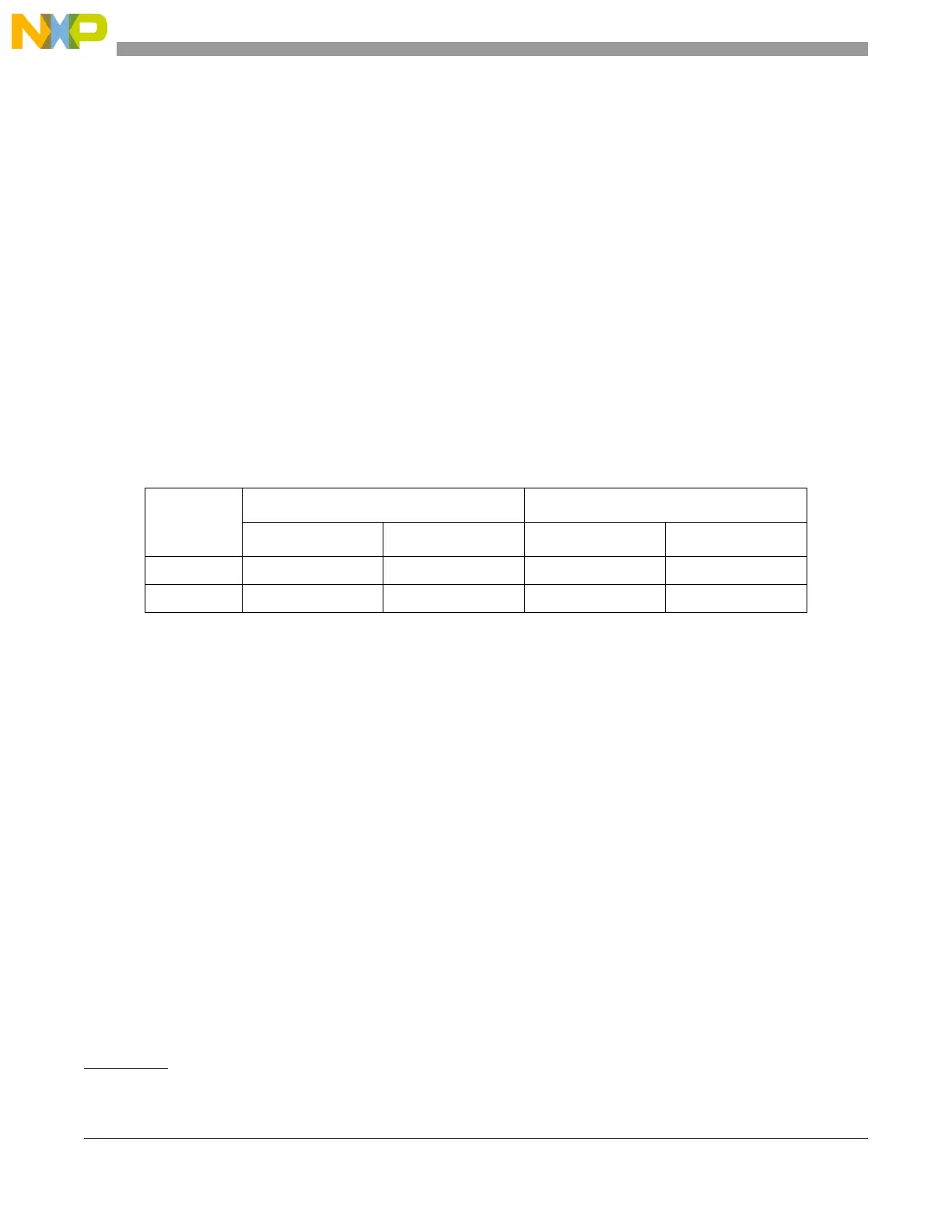
Table 19-58 shows, for this particular case, examples of how the result values change according to GCC
and OCC when result calibration is executed (CAL=1) and when it is not (CAL=0).
19.5.6.3 Quantization Error Reduction During Calibration
Figure 19-68 shows how the ADC transfer curve changes due to the addition of two to the MAC output
during the calibration. See MAC output equation in Section 19.4.5.4, “ADC Calibration Feature.” The
maximum absolute quantization error is reduced by half leading to an increase in accuracy.
1. This calculation is rounded down due to binary approximation.
Table 19-58. Calibration Example
Input Voltage
Raw result (CAL=0) Calibrated result (CAL=1)
Hexadecimal Decimal Hexadecimal Decimal
25% VREF 0x0ED6 3798 0x1000 4095.794
75% VREF 0x2D48 11592 0x3000 12287.486

 Loading...


