External Bus Interface (EBI)
MPC5566 Microcontroller Reference Manual, Rev. 2
Freescale Semiconductor 12-77
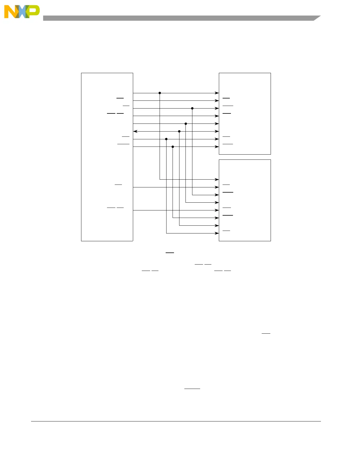
12.5.4 Connecting an MCU to Multiple Memories
The MCU can be connected to more than one memory at a time. Figure 12-55 shows an example of how
to connect two memories to one MCU.
Figure 12-55. MCU Connected to Multiple Flash Memories
12.5.5 Summary of Differences from MPC5xx
The following summary lists the significant differences between this EBI used in the MPC5xxx and that
of the MPC5xx parts:
• SETA feature is no longer available: chip select devices cannot use external TA
, instead must use
wait state configuration.
• No memory controller support for external masters: must configure each master in multi-master
system to drive its own chip selects
• Changes in bit fields:
— Removed these variable timing attributes from option register: CSNT, ACS, TRLX, EHTR
— Removed LBDIP base register bit, now late BDIP
assertion is default behavior
CLKOUT
CS
[0]
TS
WE/BE[0]
ADDR[8:29]
DATA[0:31]
BDIP
OE
MCU
CK
CE
ADV
WE **
A[0:21]
D[0:31]
OE
BAA *
SDR flash
memory
CK
CE
ADV
WE
A[0:21]
D[0:31]
OE
BAA *
SDR flash
memory
CS
[1]
WE
/BE[1]
* Connected depending on the memory used.
Flash memories typically use one WE
signal as shown.
**
Note: On a 32-bit bus, RAM memories use all four WE
/BE[0:3]. On a 16-bit bus, one
RAM memory uses WE
/BE[0:1] and the other uses WE/BE[2:3].
**
 Loading...


