Enhanced Queued Analog-to-Digital Converter (eQADC)
MPC5566 Microcontroller Reference Manual, Rev. 2
19-108 Freescale Semiconductor
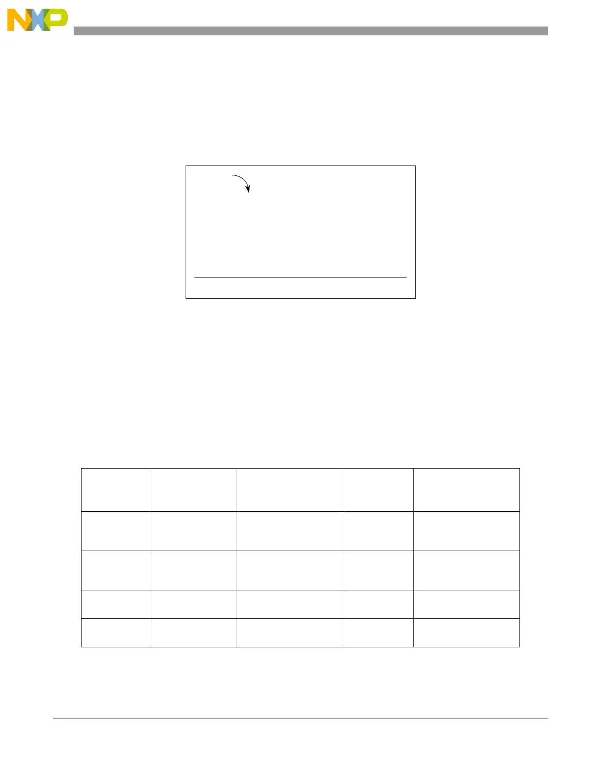
values, they are added according to the RSD algorithm to create the 12-bit digital representation of the
original analog input. The bits are added in the following manner:
19.4.9.2.3 RSD Adder
The array, s1 to s12, are the digital output of the RSD ADC with s1 being the MSB (most significant bit)
and s12 being the LSB (least significant bit).
Figure 19-63. RSD Adder
19.5 Initialization and Application Information
19.5.1 Multiple Queues Control Setup Example
This section provides an example of how to configure multiple user command queues. Table 19-56
describes how each queue can be used for a different application. Also documented in this section are
general guidelines on how to initialize the on-chip ADCs and the external device, and how to configure
the command queues and the eQADC.
Table 19-56. Example Applications of Each Command Queue
Command
Queue Number
Queue Type Running Speed
Number of
Contiguous
Conversions
Example
0 Very fast burst
time-based queue
Every 2 μs for 200 μs;
pause for 300 μs and then
repeat
2 Injector current profiling
1Fast
hardware-triggered
queue
Every 900 μs 3 Current sensing of PWM
controlled actuators
2 Fast repetitive
time-based queue
Every 2 ms 8 Throttle position
3 Software-triggered
queue
Every 3.9 ms 3 Command triggered by
software strategy
b1
a13
Carry
b12
b11
a3
a2
a12
b2
• • •
• • ••••
•••b10
a11
s1
+
s2• • ••••s10s11s12

 Loading...


