Enhanced Modular Input/Output Subsystem (eMIOS)
MPC5566 Microcontroller Reference Manual, Rev. 2
Freescale Semiconductor 17-33
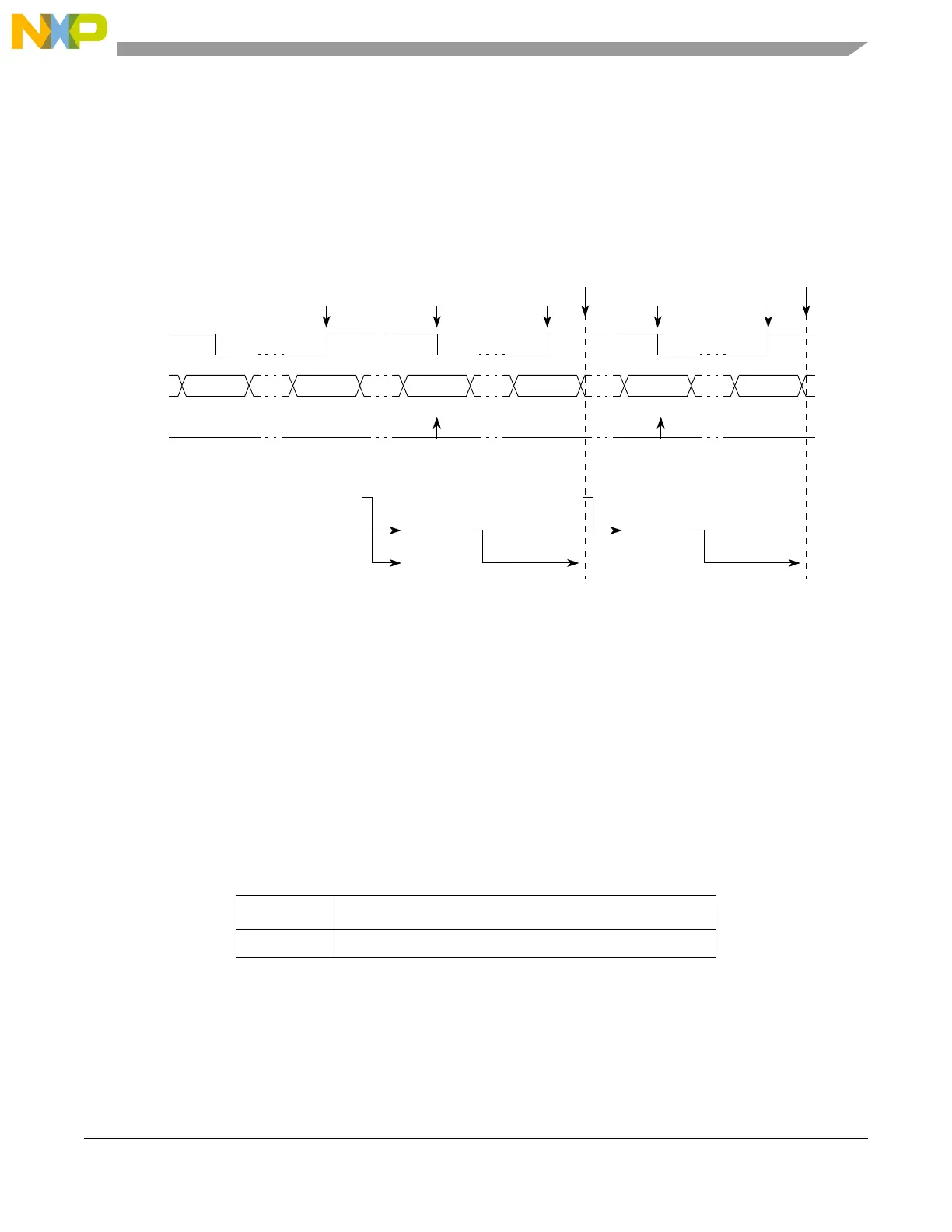
Figure 17-20 shows the A1 and B1 updates when EMIOS_CADRn and EMIOS_CBDRn register reads
occur. The A1 register always has coherent data related to the A2 register. Note also that when an
EMIOS_CADRn read is performed, the B1 register is loaded with A1 register content. This guarantee that
the data in register B1 always has the coherent data related to the last EMIOS_CADRn read. The B1
register updates remains locked until an EMIOS_CBDRn read occurs. If an EMIOS_CADRn read is
performed, the B1 register is updated with A1 register content even if the B1 update is locked by a previous
EMIOS_CADRn read operation.
Figure 17-20. B1 and A1 Updates at EMIOS_CADRn and EMIOS_CBDRn Reads
Reading EMIOS_CADRn followed by EMIOS_CBDRn always provides coherent data. If coherent data
is not required, invert the sequence of reads; read EMIOS_CBDRn before reading EMIOS_CADRn. If B1
register updates are blocked after an EMIOS_CADRn read, a second EMIOS_CBDRn read is required to
release B1 register updates.
17.4.4.4.5 Input Period Measurement Mode (IPM)
The following table lists the input period measurement mode setting:
The IPM mode allows the measurement of the period of an input signal by capturing two consecutive rising
edges or two consecutive falling edges. Successive input captures are done on consecutive edges of the
same polarity. The edge polarity is defined by the EDPOL bit in the EMIOS_CCRn.
Table 17-18. IPM Operating Mode
MODE[0:6] Unified Channel IPM Operating Mode
0b0000101 Input period measurement mode
0x000500 0x001000 0x001100 0x001250 0x001525 0x0016A0
Selected
counter bus
FLAG
set event
BBB
Captured A2
value
2
0xxxxxxx
Notes:
1
After input filter.
2
Reading EMIOS_CADRn returns the value of A2.
Input signal
1
EDPOL = 1 A A
B1 value
3
0x0015250x001100
0xxxxxxx
0xxxxxxx
0x001000 0x001250
0x001000
Captured B2
value
3
Reading EMIOS_CBDRn returns the value of B1.
0xxxxxxx 0x001000 0x0012500x001000
A1 value
3
0x001250
Read MTSA[n] Read MTSB[n]
0x0016A0

 Loading...


