Enhanced Time Processing Unit (eTPU)
MPC5566 Microcontroller Reference Manual, Rev. 2
Freescale Semiconductor 18-3
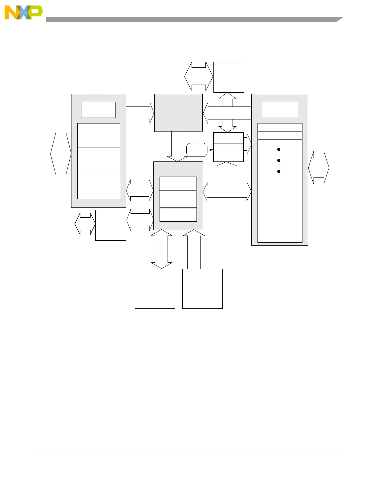
Figure 18-2 shows the block diagram for the eTPU engine.
Figure 18-2. eTPU Engine Block Diagram
18.1.3 eTPU Operation Overview
The eTPU is a real-time microprocessed subsystem. Therefore, it runs microengine code from instruction
memory (SCM) to handle specific events and accesses data memory (SDM) for parameters, work data, and
application state information. Events can originate from I/O channels (due to pin transitions and/or time
base matches), device core requests, or inter-channel requests. Events that call for local eTPU processing
activate the microengine by issuing a service request. The service request microcode can send an interrupt
to the device core, but cannot directly interrupt the core using I/O channel events.
Each channel has a function that consists of a set of microengine routines, called threads, that service eTPU
requests which defines the channel’s behavior. Function routines, which reside in the SCM, are also used
to configure the channel. A function can be assigned to several channels, but a channel can only process
TCR1
TCR2 /
microengine
code
Host
interface
Channel
control
Time base
configuration
Engine
configuration
Scheduler
Control and data
Control
Timer
channels
Channel 0
Channel 1
Channel 31
Channel
Control
TCRCLK
Pin
Mul/Div/MAC
Angle clock
Service requests
(SCM)
data
memory
Shared
(SDM)
Shared
memory
Fetch and
decode
Execution
Data
Code
unit
Debug
interface
NDEDI
Control
and data
Pins
STAC
bus
STAC
interface
To
host
to