Enhanced Modular Input/Output Subsystem (eMIOS)
MPC5566 Microcontroller Reference Manual, Rev. 2
Freescale Semiconductor 17-5
17.2 External Signal Description
Each unified channel has one input and one output signal connected to the channel’s I/O pin. Refer to the
SIU and DSPI sections for details about the connection to pads and other modules.
The internal output disable input signals 0-3 (refer to Table 17-3) are provided to implement the output
disable feature needed for motor control. They are connected to EMIOS_Flag_Out signals according to
Section 17.2.1.1, “Output Disable Input—eMIOS Output Disable Input Signals.”
17.2.1 External Signals
When configured as an input, EMIOSn is synchronized and filtered by the programmable input filter (PIF).
The output of the PIF is then used by the channel logic and is available to be read by the MCU through the
UCIN bit of the EMIOS_CSRn.
When configured as an output, EMIOSn is a registered output and is available for reading by the MCU
through the UCOUT bit of the EMIOS_CSRn.
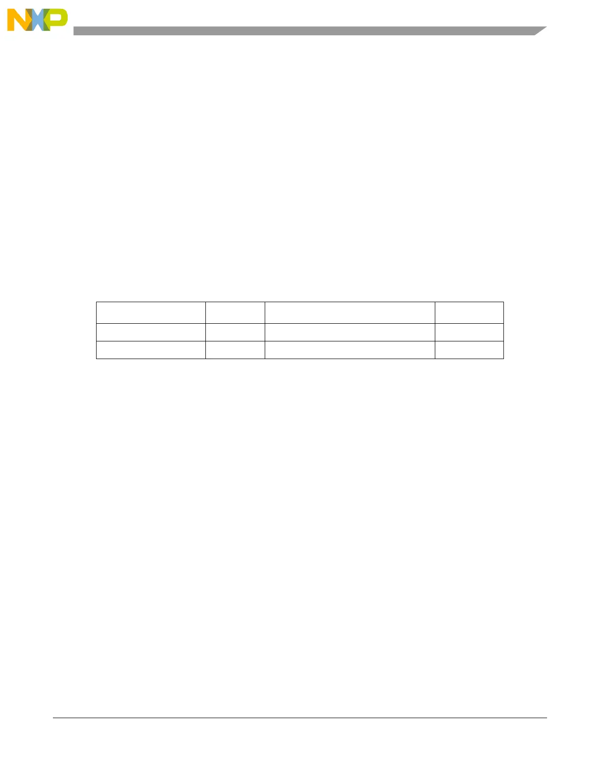
Table 17-2. External Signals
Signal Direction Function Reset State
EMIOS[0:11, 16:23] Input eMIOS Unified Channel n input —
EMIOS[0:23] Output eMIOS Unified Channel n output 0 / Hi-Z
1
1
A value of 0 refers to the reset value of the signal. Hi-Z refers to the state of the external pin if a tri-state
output buffer is controlled by the corresponding eMIOS signal.