Enhanced Modular Input/Output Subsystem (eMIOS)
MPC5566 Microcontroller Reference Manual, Rev. 2
Freescale Semiconductor 17-57
17.4.4.4.15 Modulus Counter Buffered Mode (MCB)
The following table lists the modulus counter buffered mode settings:
The MCB mode provides a time base which can be shared with other channels through the internal counter
buses. Register A1 is double buffered, thus allowing smooth transitions between cycles when changing the
A2 register value asynchronously. The A1 register is updated at the cycle boundary, which is defined as
when the internal counter reaches the value one. The internal counter values are within a range from one
up to register A1 value in MCB mode.
The MODE[6] bit selects the internal clock source if clear or external if set. When an external clock is
selected, the channel input pin is used as the channel clock source. The active edge of this clock is defined
by EDPOL and EDSEL bits in the EMIOS_CCR channel register.
When entering the MCB mode, if up counter is selected (MODE[4] = 0), the internal counter starts
counting up from its current value to until an A1 match occurs. On the next system clock cycle after an A1
match occurs, the internal counter is set to one and the counter continues counting up. If up/down mode is
selected (MODE[4] = 1), the counter changes direction at the A1 match and counts down until it reaches
one and is then set to count up again. In this mode B1 is set to one and cannot be changed, as it is used to
generate a match to switch from down count to up count.
The MCB mode counts between one and the A1 register value. The counter cycle period in up count mode
is equal to the A1 value. In up/down counter mode the period is defined by the formula: (2 × A1) – 2.
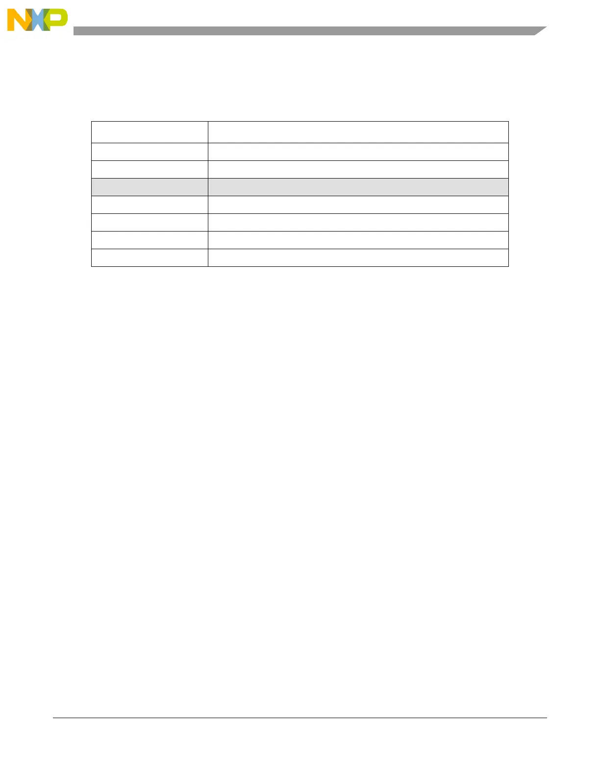
Table 17-28. MCB Operating Modes
MODE[0:6] Unified Channel MCB Operating Mode
0b1010000 Modulus up counter, buffered, internal clock
0b1010001
Modulus up counter, buffered, external clock
0b1010010–0b1010001 Reserved
0b1010100 Modulus up/down counter, buffered. FLAG set on one event, internal clock.
0b1010101 Modulus up/down counter, buffered. FLAG set on one event, external clock.
0b1010110 Modulus up/down counter, buffered. FLAG set on both events, internal clock.
0b1010111 Modulus up/down counter, buffered. FLAG set on both events, external clock.