Enhanced Modular Input/Output Subsystem (eMIOS)
MPC5566 Microcontroller Reference Manual, Rev. 2
17-24 Freescale Semiconductor
Figure 17-11 provides a block diagram for the STAC client submodule.
Figure 17-11. STAC Client Submodule Block Diagram
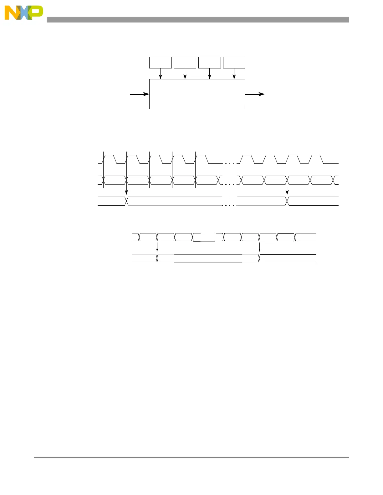
Bits SRV[0:3] in register EMIOS_MCR, selects the time slot of the STAC output bus. Figure 17-12 shows
a timing diagram for the STAC client submodule.
Figure 17-12. Timing Diagram for the STAC Bus and
STAC Client Submodule Output
Every time the selected time slot changes, the STAC client submodule output is updated.
17.4.2.1 Effect of Freeze on the STAC Client Submodule
When the FRZ bit in the EMIOS_MCR is set and the module is in debug mode, the operation of the STAC
client submodule is not affected; that is, there is no freeze function in this submodule.
17.4.3 Global Clock Prescaler Submodule (GCP)
The global trace prescaler divides the system clock to generate a clock for the unified channels. The system
clock is prescaled by the value defined according to the GPRE[0:7] bits in the EMIOS_MCR. The output
is clocked every time the counter overflows. Counting is enabled by setting EMIOS_MCR[GPREN]. The
counter can be stopped at any time by clearing this bit, thereby stopping the internal counter in all the
unified channels.
SRV3 SRV2 SRV1 SRV0
STAC bus Time base
STAC client submodule
(24-bit wide) output
Time slot selector bits
TS[02]
STAC bus
(submodule input)
TS[00] TS[01] TS[02]
Time base
(submodule output)
TS[01]xx
The SRV bits are set to capture TS[01].
TS[03] TS[00] TS[03] TS[00] TS[01]
System clock
TS[01]
STAC bus (REDC input)
TS[00] TS[01] TS[02]
1. Maximum of 16 time slots (TSn)
NOTES:
TS[01]TS[00]
TSn1
TS[02]
Time base (REDC output)
TS[01]
TS[01]
xx
2. The SRV bits capture TS[01]

 Loading...


