Enhanced Queued Analog-to-Digital Converter (eQADC)
MPC5566 Microcontroller Reference Manual, Rev. 2
Freescale Semiconductor 19-91
19.4.5.5 ADC Control Logic Overview and Command Execution
Figure 19-51 shows the basic logic blocks involved in the ADC control and how they interact.
CFIFOs/RFIFOs interact with ADC command/result message return logic through the FIFO control unit.
The EB and BN bits in the command message uniquely identify the ADC to which the command is sent.
The FIFO control unit decodes these bits and sends the ADC command to the proper ADC. Other blocks
of logic are the result format and calibration submodule, the time stamp logic, and the MUX control logic.
0 1 23456789101112131415
GCC_INT GCC_FRAC
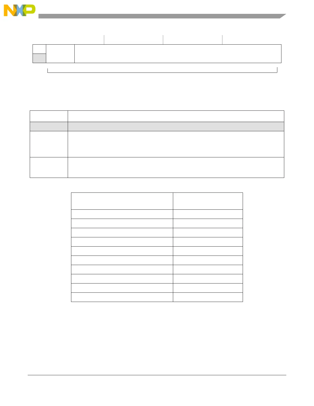
Figure 19-50. Gain Calibration Constant Format
Table 19-48. Gain Calibration Constant Format Field Descriptions
Field Description
0 Reserved
1
GCC_INT
Integer part of the gain calibration constant for ADCn. GCC_INT is the integer part of the gain calibration
constant (GCC) for ADC0/1.
0 = ADC0
1 = ADC1
2–15
GCC_FRAC
[1:14]
Fractional part of the gain calibration constant for ADCn. GCC_FRAC is the fractional part of the gain
calibration constant (GCC) for ADCn. GCC_FRAC can expresses decimal values ranging from 0 to
0.999938...
Table 19-49. Correspondence between Binary and Decimal Representations of the Gain Constant
Gain Constant
(GCC_INT.GCC_FRAC binary format)
Corresponding Decimal Value
0.0000_0000_0000_00 0
... ...
0.1000_0000_0000_00 0.5
... ...
0.1111_1111_1111_11 0.999938...
1.0000_0000_0000_00 1
... ...
1.1100_0000_0000_00 1.75
... ...
1.1111_1111_1111_11 1.999938...
Gain Calibration Constant (GCC)
 Loading...