System Integration Unit (SIU)
MPC5566 Microcontroller Reference Manual, Rev. 2
Freescale Semiconductor 6-21
The following table describes the fields in the IRQ falling-edge event enable register:
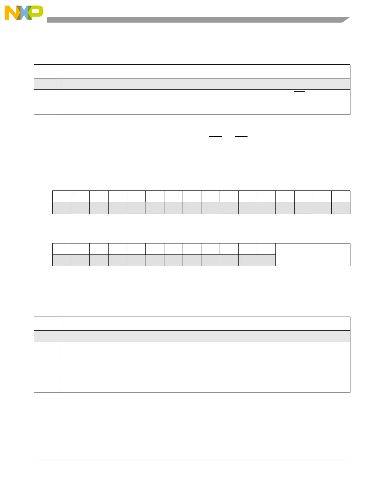
6.3.1.11 IRQ Digital Filter Register (SIU_IDFR)
The SIU_IDFR specifies the amount of digital filtering on IRQ[0]–IRQ[15]. The digital filter length field
specifies the number of system clocks that define the period of the digital filter and the minimum time an
IRQ signal must hold the active state to qualify as an edge-triggered event.
The following table describes the field in the IRQ digital filter register:
Table 6-17. SIU_IFEER Field Descriptions
Field Function
0–15 Reserved
16–31
IFEEn
IRQ falling-edge event enable n. Enables falling-edge-triggered events on the corresponding IRQ[n] pin.
0 Falling-edge event is disabled.
1 Falling-edge event is enabled.
Address: Base + 0x0030 Access: R/W
0123456789101112131415
R0000000000000000
W
Reset0000000000000000
16 17 18 19 20 21 22 23 24 25 26 27 28 29 30 31
R000000000000
DFL
W
Reset0000000000000000
Figure 6-12. IRQ Digital Filter Register (SIU_IDFR)
Table 6-18. SIU_IDFR Field Descriptions
Field Function
0–27 Reserved
28–31
DFL
Digital filter length. Defines the digital filter period on the IRQn inputs according to the following equation:
For a 100 MHz system clock, this gives a range of 20 ns to 328 µs. The minimum time of three clocks accounts for
synchronization of the IRQ input pins with the system clock.
Filter Period SystemClockPeriod 2
DFL
×()1S( ystemClockPeriod)+=

 Loading...


