MPC5566 Microcontroller Reference Manual, Rev. 2
Freescale Semiconductor 22-31
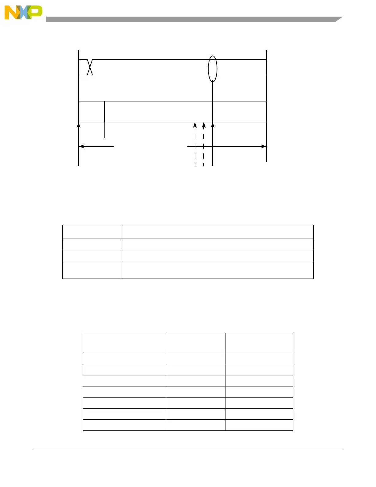
Figure 22-14. Segments within the Bit Time
Table 22-17 describes the time segment syntax:
Table 22-18 gives an overview of the CAN compliant segment settings and the related parameter values.
NOTE
Ensure the bit time settings are in compliance with the CAN standard.
Table 22-17. Time Segment Syntax
Syntax Description
SYNCSEG System expects transitions to occur on the bus during this period.
Transmit point A node in transmit mode transfers a new value to the CAN bus at this point.
Sample point A node in receive mode samples the bus at this point. If the three samples per
bit option is selected, then this point marks the position of the third sample.
Table 22-18. CAN Standard Compliant Bit Time Segment Settings
Time Segment 1 Time Segment 2
Resynchronization
Jump Width
5 .. 10 2 1 .. 2
4 .. 11 3 1 .. 3
5 .. 12 4 1 .. 4
6 .. 13 5 1 .. 4
7 .. 14 6 1 .. 4
8 .. 15 7 1 .. 4
9 .. 16 8 1 .. 4
SYNCSEG
Time segment 1 Time segment 2
1 4 ... 16 2 ... 8
8 ... 25 time quanta = 1 bit time
NRZ signal
Sample point
(single or triple sampling)
(PROPSEG + PSEG1 + 2) (PSEG2 + 1)
Transmit Point

 Loading...


