Enhanced Queued Analog-to-Digital Converter (eQADC)
MPC5566 Microcontroller Reference Manual, Rev. 2
Freescale Semiconductor 19-97
Figure 19-53 shows the maximum configuration of four external multiplexer chips connected to the
eQADC. The external multiplexer chip selects one of eight analog inputs and connects it to a single analog
output, which is fed to a specific input of the eQADC. The eQADC provides three multiplexed address
signals, MA[0], MA[1], and MA[2], to select one of eight inputs. These three multiplexed address signals
are connected to all four external multiplexer chips. The analog output of the four multiplex chips are each
connected to four separate eQADC inputs, ANW, ANX, ANY, and ANZ. The MA pins correspond to the
three least significant bits of the channel number that selects ANW, ANX, ANY, and ANZ with MA[0]
being the most significant bit. Refer to Table 19-53.
When the external multiplexed mode is selected for either ADC, the eQADC automatically creates the MA
output signals from CHANNEL_NUMBER field of a command message. The eQADC also converts the
proper input channel (ANW, ANX, ANY, and ANZ) by interpreting the CHANNEL_NUMBER field. As
a result, up to 32 externally multiplexed channels appear to the conversion queues as directly connected
signals.
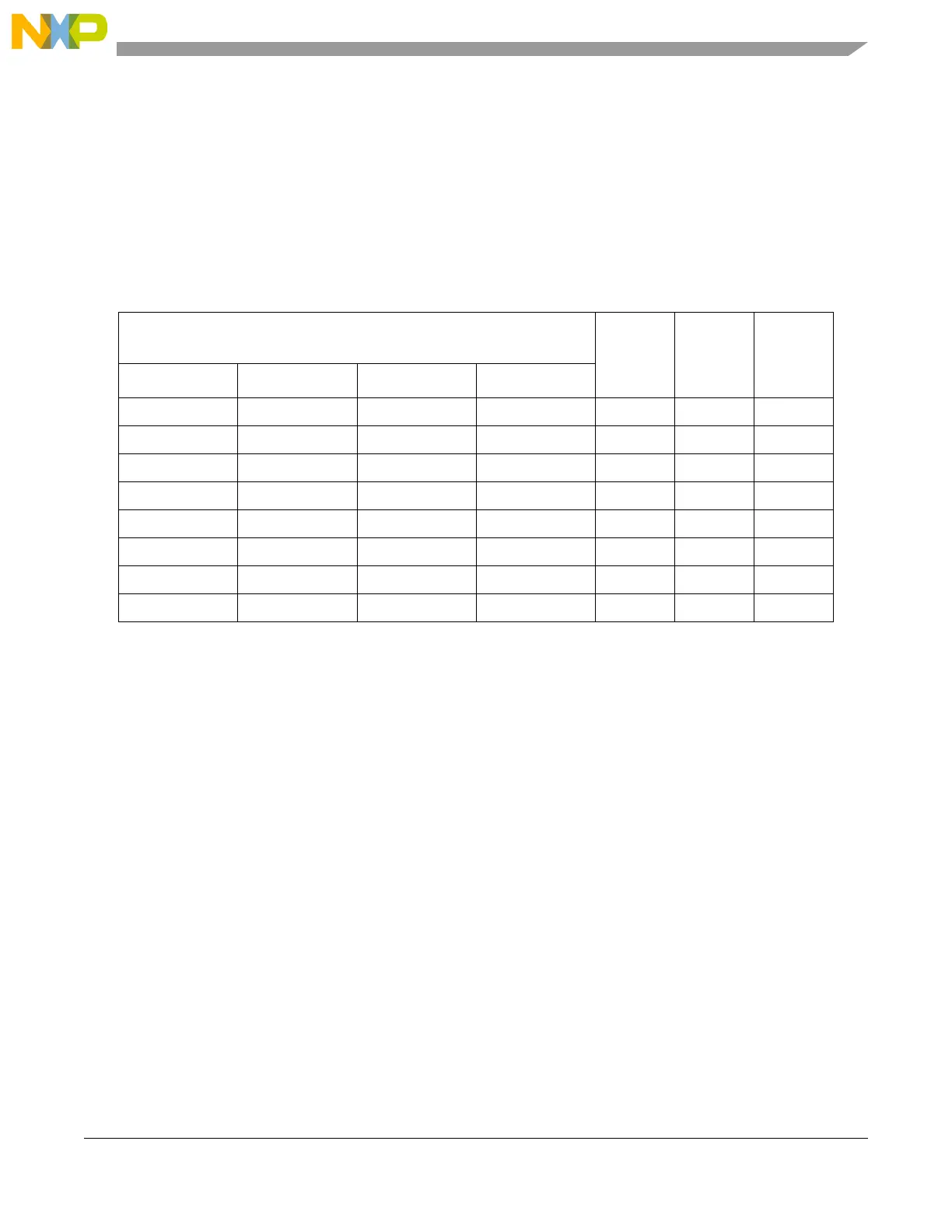
Table 19-53. Encoding of MA Pins
1
1
0 means pin is driven LOW and 1 that pin is driven HIGH.
Channel Number selecting ANW, ANX, ANY, ANZ
(decimal)
MA0 MA1 MA2
ANW ANX ANY ANZ
64 72 80 88 0 0 0
65 73 81 89 0 0 1
66 74 82 90 0 1 0
67 75 83 91 0 1 1
68 76 84 92 1 0 0
69 77 85 93 1 0 1
70 78 86 94 1 1 0
71 79 87 95 1 1 1

 Loading...


