Frequency Modulated Phase Locked Loop and System Clocks (FMPLL)
MPC5566 Microcontroller Reference Manual, Rev. 2
Freescale Semiconductor 11-31
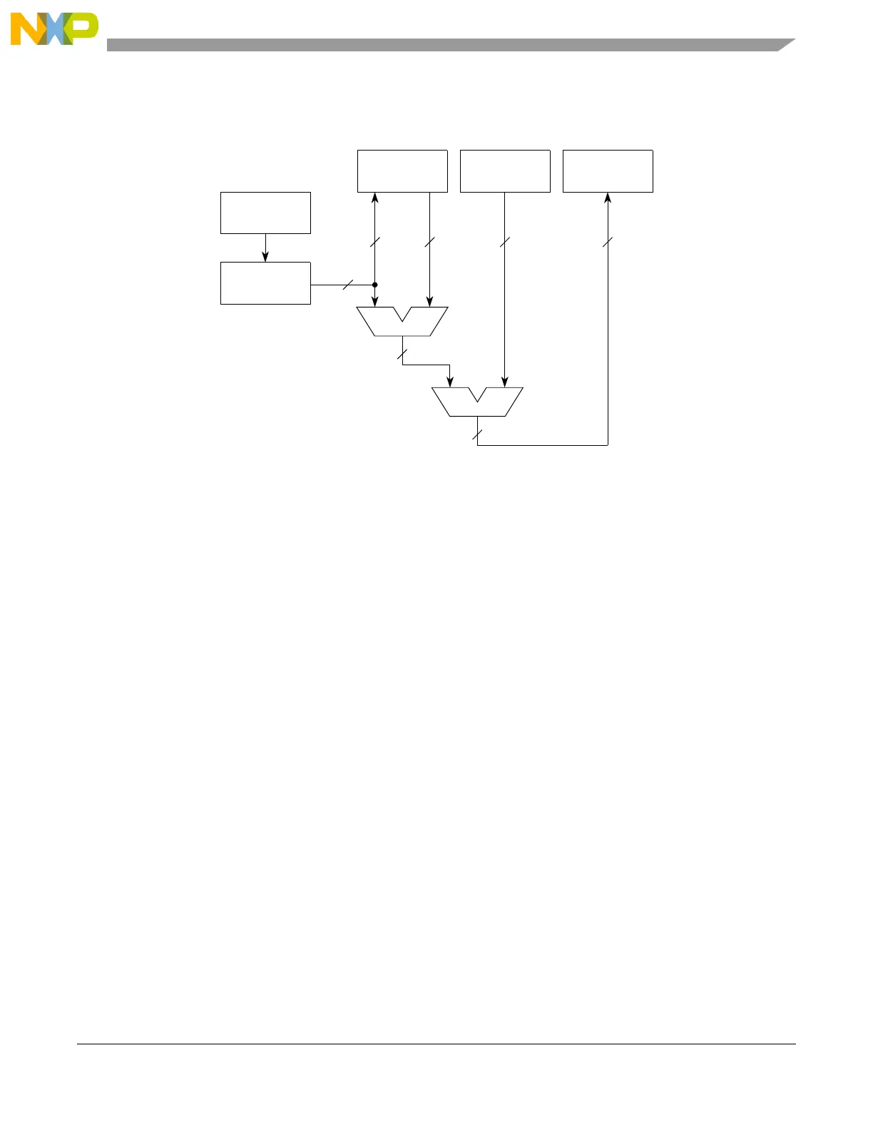
Figure 11-11 shows a block diagram of the calibration circuitry and its associated registers. Figure 11-12
shows a flow chart showing the steps taken by the calibration circuit.
Figure 11-11. FM Auto-Calibration Data Flow
Reference
counter
ICO
counter
10
13
Count 0
10
Expected
(EXP)
Error
(ERR)
13 13 10 10
A
B
CD
Control
A – B = Delta count
C–D = Error count