Enhanced Modular Input/Output Subsystem (eMIOS)
MPC5566 Microcontroller Reference Manual, Rev. 2
Freescale Semiconductor 17-65
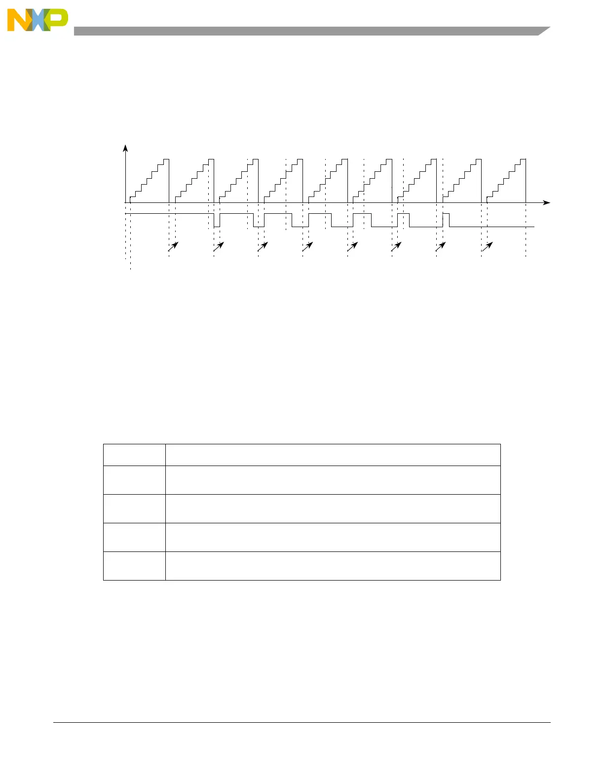
Figure 17-48 illustrates the generation of 100% and 0% duty cycle signals. It is assumed that EDPOL = 0
and the prescaler ratio is 1. Initially A1 = 0x000008 and B1 = 0x000008. In this case, a B1 match has
precedence over an A1 match, thus the output flip-flop is set to the complement of EDPOL. This cycle
corresponds to a 100% duty cycle signal. The same output signal can be generated for any A1 value greater
than or equal to B1.
Figure 17-48. eMIOS OPWFMB Mode Example — 100% to 0% Duty Cycle
A 0% duty cycle signal is generated if A1 = 0 as shown in Figure 17-48 cycle 9. In this case the
B1 = 0x000008 match from cycle 8 occurs at the same time as the A1 = 0x000000 match from cycle 9.
Refer to Figure 17-45 for a description of A1 and B1 match generation for a case where A1 match has
precedence over B1 match and the output signal transitions to EDPOL.
17.4.4.4.17 Center-Aligned Output Pulse-Width Modulation Buffered Mode (OPWMCB)
The following table lists the center-aligned output pulse-width modulation buffered mode settings:
This mode generates a center-aligned PWM with dead time insertion on the leading or trailing edge. A1
and B1 registers are double buffered to allow smooth output signal generation when changing A2 or B2
values asynchronously.
The selected counter bus for a channel configured to OPWMCB mode must be another channel running
in MCB up/down counter mode (refer to Section 17.4.4.4.15, “Modulus Counter Buffered Mode (MCB)”).
Register A1 contains the ideal duty cycle for the PWM signal and is compared with the selected time base.
Register B1 contains the dead time value and is compared against the internal counter. For a leading edge
Table 17-30. OPWMCB Operating Modes
MODE[0:6] Unified Channel OPWMCB Operating Mode
0b1011100 Center-aligned output pulse-width modulation, buffered. FLAG set on trailing edge,
trailing edge dead-time.
0b1011101 Center-aligned output pulse-width modulation, buffered. FLAG set on trailing edge,
leading edge dead-time.
0b1011110 Center-aligned output pulse-width modulation, buffered. FLAG set on both edges,
trailing edge dead-time.
0b1011111 Center-aligned output pulse-width modulation, buffered. FLAG set on both edges,
leading edge dead-time.
0x000008 0x000007 0x000006 0x000005 0x000004 0x000003 0x000002 0x000001 0x000000
0%
100%
EMIOS_CCNTRn
EDPOL = 0
A1 value
B1 value
Output flip-flop
0x000008
Prescaler = 1
Cycle 1 Cycle 2 Cycle 3 Cycle 4 Cycle 5 Cycle 6 Cycle 7 Cycle 8 Cycle 9
0x000007 0x000006 0x000005 0x000004 0x000003 0x000002 0x000001 0x000000
A2 value
Time

 Loading...


