Power analysis (option R&S RTE-K31)
R&S
®
RTE
1012User Manual 1326.1032.02 ─ 20
●
POWer:RIPPle:RESult:STDDev:STDDev? on page 1978
●
POWer:RIPPle:RESult:STDDev:WFMCount? on page 1978
●
POWer:RIPPle:RESult:STDDev[:ACTual]? on page 1978
●
POWer:RIPPle:REPort:ADD on page 1974
16.6.1.2 Configuring output ripple
For details of the configuration settings, see Chapter 16.6.1.3, "Output ripple settings",
on page 1013.
1. Select "Analysis" > "Power".
2. Under "Output", select "Ripple".
3. Connect the voltage probe to the oscilloscope.
4. If you want to measure the current ripple, enable the current channel .Connect the
current probe to the oscilloscope.
5. If you want to measure both the voltage and the current ripple, deskew the probes
as described in Chapter 16.1.1.1, "Auto deskew", on page 955.
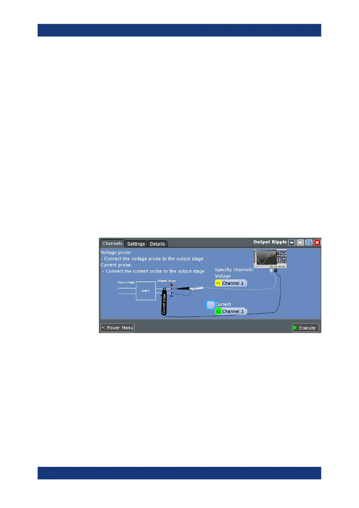
6. Connect the probes to the DUT as shown in the "Channels" tab:
7. Select the correct channels for the "Voltage Source" and the "Current Source".
8. Select the "Settings" tab.
9. Set the "SMPS switching frequency" according to your signal.
10. Select an "Optimize Scaling" option.
11. Tap "Execute".
On the screen, you can see the measurement waveforms of the current and the
voltage. Also, the result box with numeric measurement results is shown. For
details, see Chapter 16.6.1.1, "Output ripple results", on page 1008.
Output

 Loading...


