Power analysis (option R&S RTE-K31)
R&S
®
RTE
1016User Manual 1326.1032.02 ─ 20
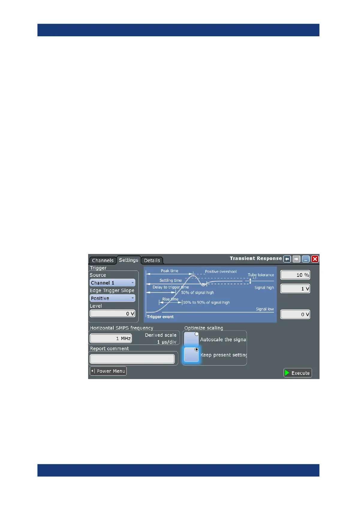
8. Set the "Trigger" settings according to your signal.
9. Set the "Tube tolerance", "Signal high" and "Signal low" according to your require-
ments.
10. Set the "SMPS switching frequency" according to your device.
11. Select an "Optimize Scaling" option.
12. Tap "Execute".
13. If needed adjust the cursors manually.
You can tap on a cursor and change its position with the [NAVIGATION] rotary
knob.
On the screen, you can see the measurement of the current and the voltage . Also,
there is a table giving information about important measurement parameters. For
details, see Chapter 16.6.2.1, "Transient response results", on page 1014.
16.6.2.3 Transient response settings
In the "Channels" tab, you set the current source and the voltage sources, see also:
Chapter 16.2.1, "Channels tab", on page 965 and POWer:TRANsient:INPut
on page 1979.
In the "Settings" tab, you configure the transient response measurement parameters
and display settings.
Trigger
Sets the properties of the trigger.
Source ← Trigger
Sets the source channel of the trigger.
Remote command:
POWer:TRANsient:TRGChannel on page 1980
Output

 Loading...


