Mixed signal option (MSO, R&S RTE-B1)
R&S
®
RTE
909User Manual 1326.1032.02 ─ 20
14.2.2 Adjusting the display of digital channels and parallel buses
The display of digital channels and parallel buses is flexible, you can adjust it to your
needs by combining the following settings:
1. Enable "Show bus" if you want to display the bus signal in the diagram. Under "Bus
representation", select if you want to display the decoded bus signal with bus val-
ues ("Comb"), or show the bus values as amplitudes, similar to an analog wave-
form ("Analog").
2. Check the signal icon of the bus to monitor the activities on the digital channels
even if they are not displayed in the diagram:
● Blue: channel is low
● Green: channel is high
● Gray: channel state is changing
3. In the diagram, you can change the display order of the digital channels by drag-
ging the individual channels to the required position.
4. To adjust the line height and vertical position of all digital channels at once, tap one
of the digital channels and turn the vertical [SCALE] and [POSITION / OFFSET]
rotary knobs. In the same way, you can move and scale the bus signal.
5. If the bus signal is displayed as quasi-analog waveform, you can double-tap the
waveform to open the "Parallel buses" dialog box.
6. To switch off the display of the digital channels, disable "Show signals".
14.3 Trigger
For digital trigger sources are all trigger types useful that require only one trigger level
as trigger condition. This level is the logical threshold. Possible trigger sources are the
individual digital channels, parallel bus signals, or any logical combination of digital
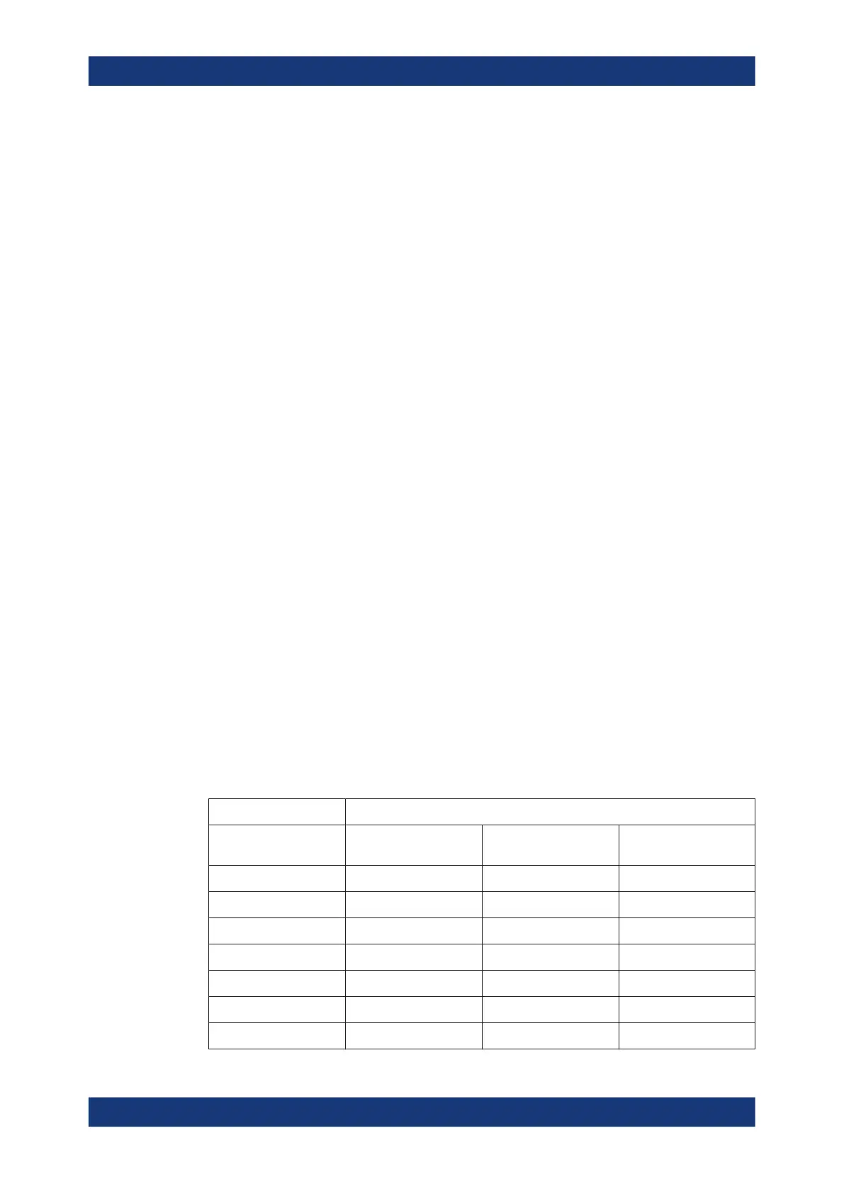
channels. The following trigger types are available:
Table 14-1: Trigger types and digital trigger sources
Trigger type Trigger source is
Digital channel Logic combination of
digital channels
Parallel bus
Edge X X
Width X X
Timeout X X
"Data2Clock" X
X
State
X X
Pattern (with holdoff)
X X
Serial Pattern X X
Trigger

 Loading...


