Power analysis (option R&S RTE-K31)
R&S
®
RTE
982User Manual 1326.1032.02 ─ 20
●
POWer:MODulation:RESult:NPEak? on page 1958
●
POWer:MODulation:RESult:PPEak? on page 1958
●
POWer:MODulation:RESult:RMS? on page 1958
●
POWer:MODulation:RESult:STDDev? on page 1958
●
POWer:MODulation:RESult:WFMCount? on page 1958
●
POWer:MODulation:REPort:ADD on page 1958
16.4.1.2 Configuring modulation analysis
For details of the configuration settings, see Chapter 16.4.1.3, "Modulation analysis
settings", on page 983.
1. Select "Analysis" > "Power".
2. Under "Switching / Control Loop", select "Modulation Analysis".
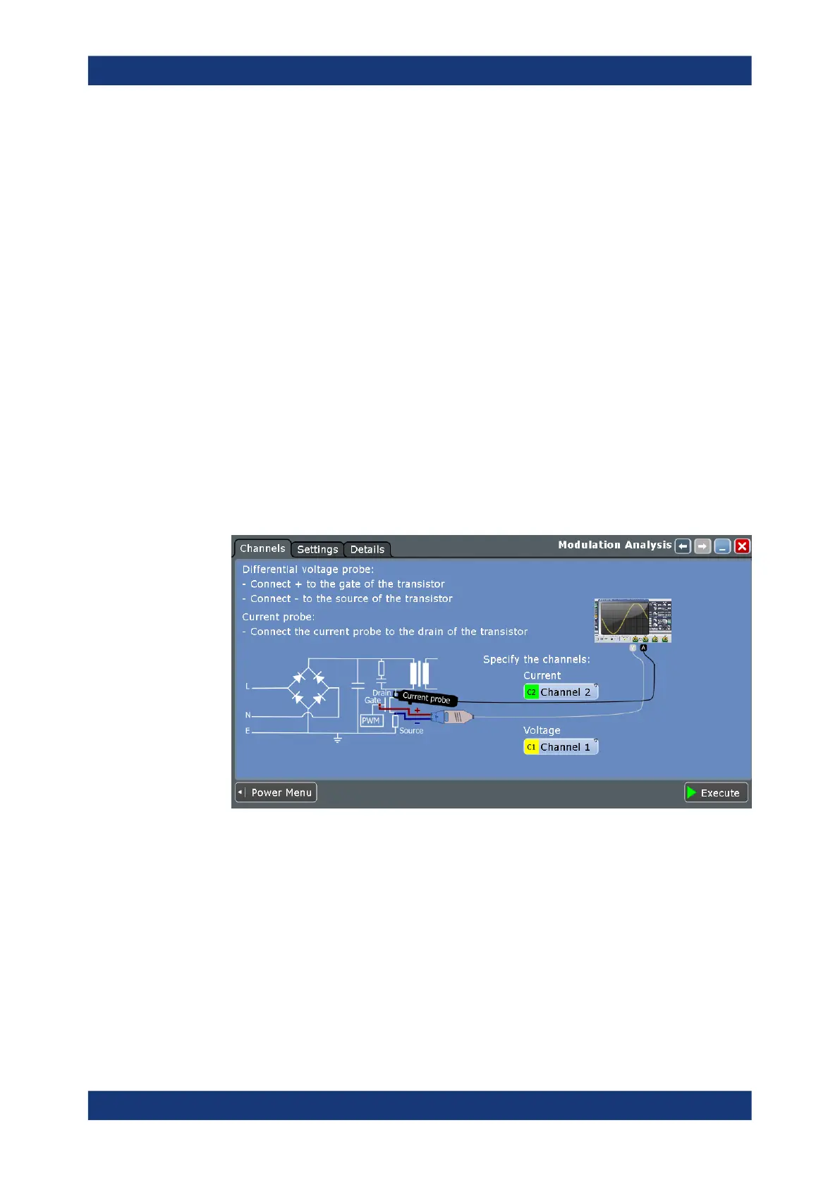
3. Connect the differential voltage probe and the current probe to the oscilloscope.
4. Deskew the probes as described in Chapter 16.1.1.1, "Auto deskew", on page 955.
5. Connect the probes to the DUT as shown in the "Channels" tab:
6. Select the correct channels for the "Current Source" and the "Voltage Source".
7. Select the "Settings" tab.
8. Set the "Source" and the "Type" of measurement.
9. Select an "Optimize Scaling" option.
10. Tap "Execute".
On the screen, you can see the measurement waveforms of the current or the volt-
age. Also, the result box with numeric measurement results is shown. For details,
see Chapter 16.4.1.1, "Modulation analysis results", on page 981.
Control loop

 Loading...


