TC1796
Peripheral Units (Vol. 2 of 2)
Asynchronous/Synchronous Serial Interface (ASC)
User’s Manual 19-5 V2.0, 2007-07
ASC, V2.0
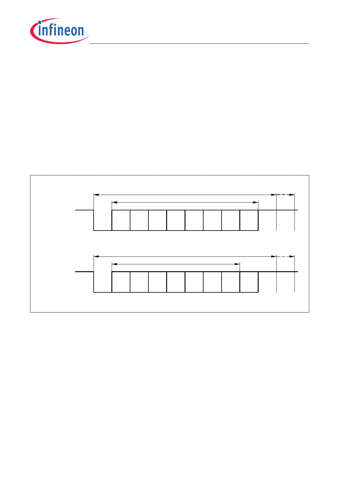
19.1.3.1 Asynchronous Data Frames
Asynchronous data frames can consist of 8-bit or 9-bit data frames.
8-Bit Data Frames
The 8-bit data frames consist of either eight data bits D7 … D0 (CON.M = 001
B
), or of
seven data bits D6 … D0 plus an automatically generated parity bit (CON.M = 011
B
).
Parity may be odd or even, depending on bit CON.ODD. An even parity bit will be set if
the modulo-2 sum of the seven data bits is 1. An odd parity bit will be cleared in this case.
Parity checking is enabled via bit CON.PEN (always OFF in 8-bit data mode). The parity
error flag CON.PE will be set, along with the error interrupt request flag, if a wrong parity
bit is received. The received parity bit itself will be stored in RBUF too.
Figure 19-3 Asynchronous 8-Bit Frames
MCT05764
D5
D0
LSB
D3D1 D2 D4
D7
MSB
D6
Start
Bit
0
(1st)
Stop
Bit
(2nd)
Stop
Bit
10-/11-Bit UART Frame
8 Data Bits
11
CON.M = 001
B
CON.M = 011
B
D5
D0
LSB
D3D1 D2 D4
Parity
Bit
D6
MSB
Start
Bit
0
(1st)
Stop
Bit
(2nd)
Stop
Bit
10-/11-Bit UART Frame
7 Data Bits
11

 Loading...