TC1796
System Units (Vol. 1 of 2)
On-Chip System Buses and Bus Bridges
User’s Manual 6-4 V2.0, 2007-07
Buses, V2.0
Note: For the LMB default master, the one cycle gap does not result in a performance
loss because it is granted the LMB in this cycle as default master if no other master
requests the LMB for some other reasons.
6.1.5 LMB Basic Operation
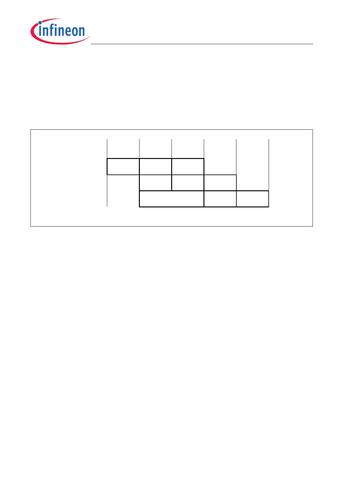
Figure 6-2 describes some basic bus operations of the LMB.
Figure 6-2 Basic LMB Transactions
Transfer 1 displays the three cycles of any LMBs transaction:
1. Request/Grant Cycle: The LMB master attempts to perform a read or write transfer
and requests for the LMB. If the LMB is available, it is granted in the same cycle by
the LMB bus controller.
2. Address Cycle: After the request/grant cycle, the master puts the address on the
LMB and all LMB slave devices check whether they are addressed for the following
data cycle.
3. Data Cycle: In the data cycle, either the LMB master puts write data on the LMB
which is read by the LMB slave (write cycle), or vice versa (read cycle).
Transfers 2 and 3 show the conflict when two masters try to use the LMB, and how the
conflict is resolved. In the example, the LMB master of transfer 2 has a higher priority
than the LMB master of transfer 3.
During a block transfer, the address cycle of a second transfer is extended until the data
cycles of the block transfer are finished. In the example shown in Figure 6-3, transfer 1
is a block transfer while transfer 2 is a single transfer.
Request /
Grant
Data
Cycle
Address
Cycle
Bus Cycle 1 2 3 4
Request /
Grant
Address
Cycle
Data
Cycle
Data
Cycle
Address
Cycle
Request /Grant
5
MCA05628_mod
Transfer 1
Transfer 2
Transfer 3

 Loading...