TC1796
Peripheral Units (Vol. 2 of 2)
Controller Area Network (MultiCAN) Controller
User’s Manual 22-146 V2.0, 2007-07
MultiCAN, V2.0
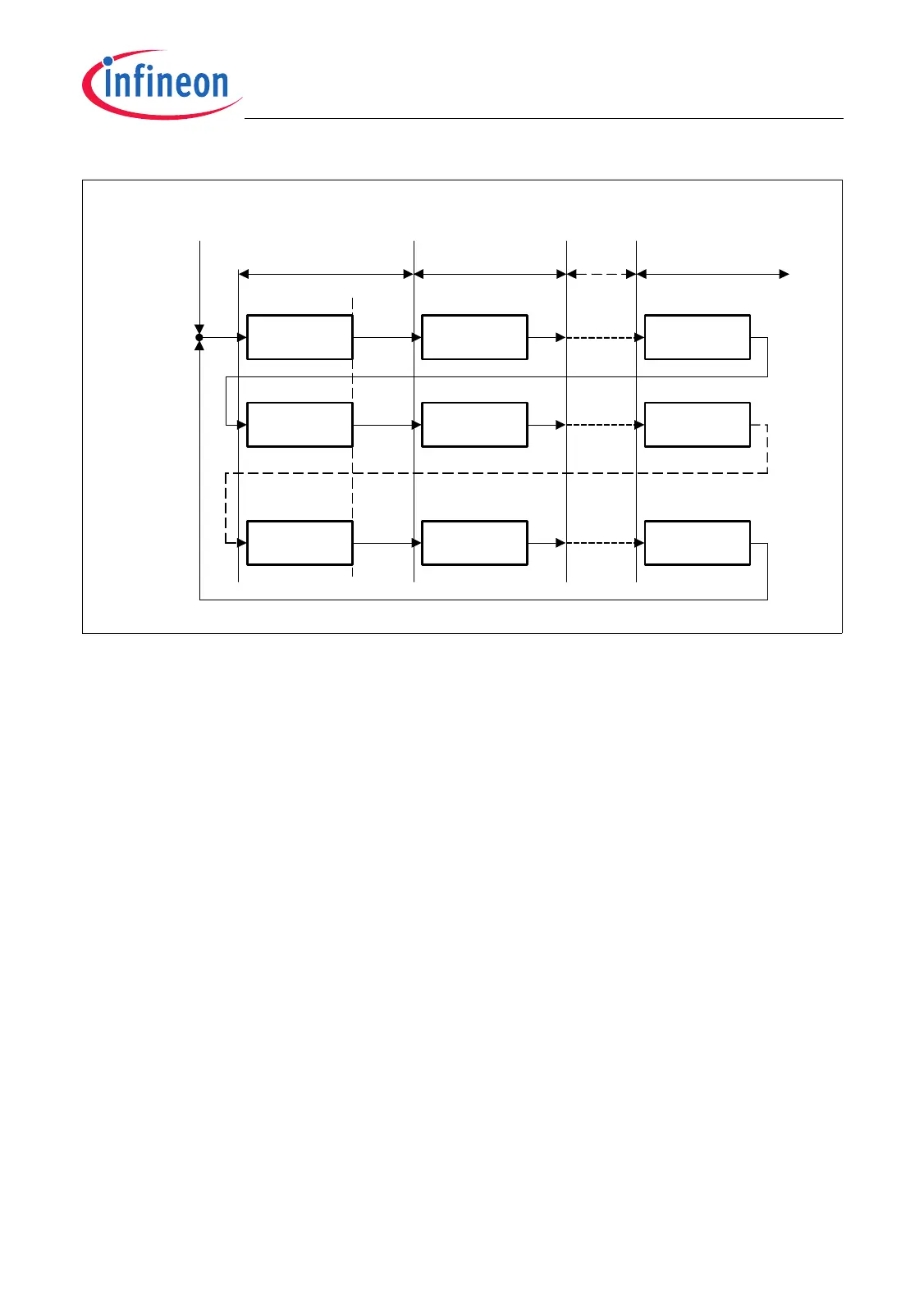
Figure 22-33 BCC and CSM in a Matrix Cycle
The cycle time of each basic cycle starts with 0 (virtual value). The start of a new basic
cycle can only be detected after the correct transfer of a reference message. As a result,
the cycle time value can be considered as valid after the reference message has been
correctly transferred.
22.6.5.2 General Instruction Sequence Rules
The settings of already read scheduler instructions can be overwritten by following valid
scheduler instructions. The following order of scheduler entry types must be respected
to set up the scheduler correctly (starting with the first):
• TME then RCE or ICE or TCE or ARBE
• RME then BCE (for time masters)
• BCE (for slave devices)
The scheduler entries must always be closed with a BCE with GM = 0.
For time masters, the following sequence can be set up to close the scheduler entries:
• RME (GM = 1) then BCE (GM = 1) then RME (GM = 0) then BCE (GM = 0)
(the entries RME(GM = 0) and BCE(GM = 0) are mandatory)
If the system is in-a-gap, the first RME and BCE entries (both with GM = 1) are not taken
into account. With these entries, the standard (not in-a-gap) timing values can be
adjusted. A second RME (with GM = 0) can be set up to send an emergency reference
message while the system is in-a-gap and the synchronization event takes too long. The
MCA05859
Reference
Message
Message 11 Message 1n
Reference
Message
Message 21 Message 2n
Reference
Message
Message m1 Message mn
BCC = 0
CSM = 0
BCC = m CSM = n BCC = 0 CSM = 1 BCC = 0 CSM = n
Time
Mark 1
Time
Mark 2
Time
Mark n
BCC = 0 CSM = n BCC = 1 CSM = 1 BCC = 1 CSM = n
BCC = m CSM = 1 BCC = m CSM = n
EOF
Configuration
Mode Left
Reference Window Time Window 1 Time Window n
BCC = m CSM = n
BCC = 0
CSM = 0
BCC = 1
CSM = 0
BCC = m
CSM = 0

 Loading...