TC1796
Peripheral Units (Vol. 2 of 2)
Analog-to-Digital Converter (ADC)
User’s Manual 25-110 V2.0, 2007-07
ADC, V2.0
25.3.4.2 Pad Output Driver Characteristics Selection
The Port 7 pad driver mode register contains bit fields that determine the output driver
strength and the slew rate of ADC external multiplexer control outputs (class A1 outputs).
Table 25-15 PCx Coding for ADC Outputs
PCx[3:0] I/O Output
Characteristics
Selected Pull-up / Pull-down /
Selected Output Function
1011
B
Output Push-pull Output function ALT1
1111
B
Open-drain Output function ALT1
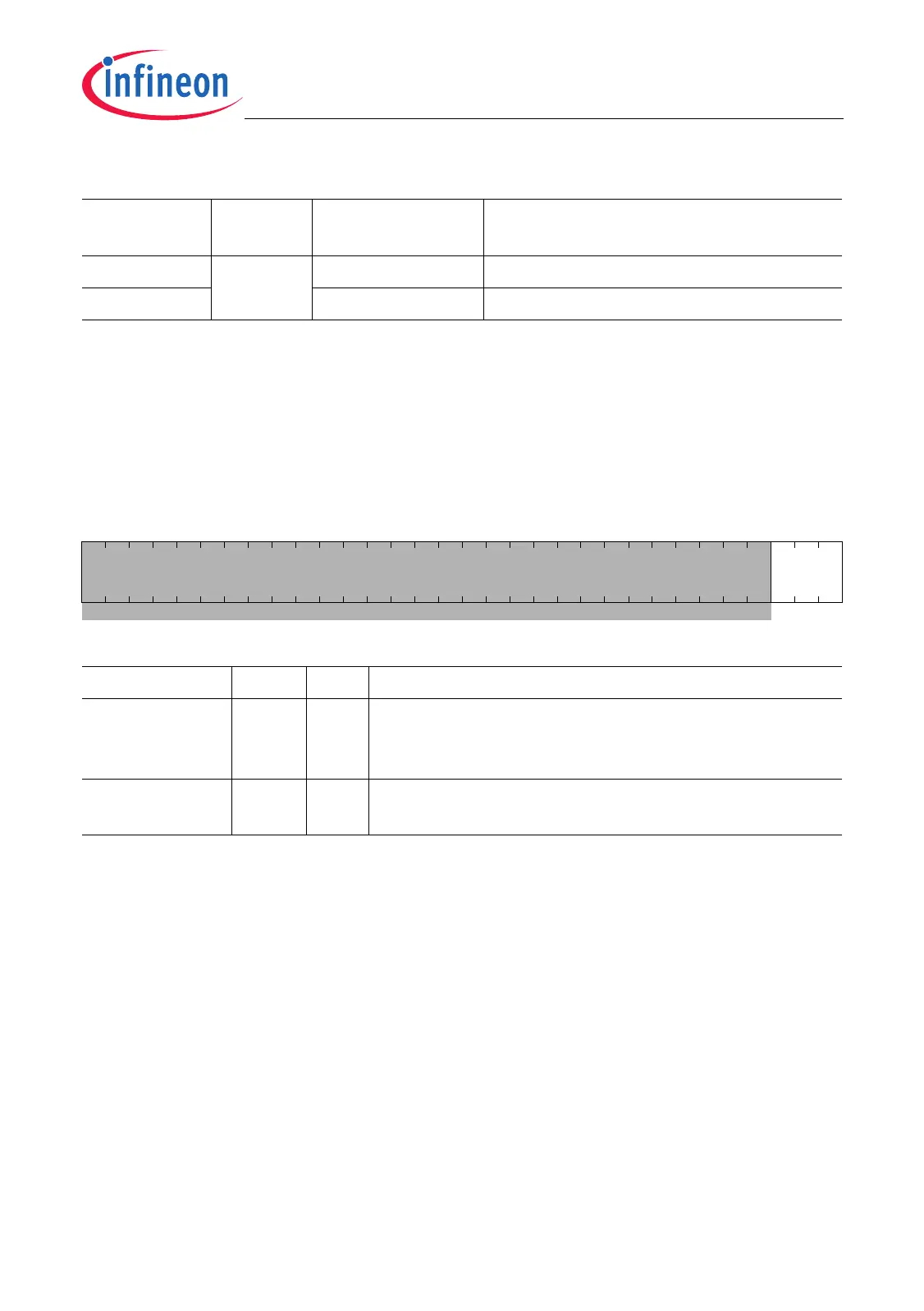
P7_PDR
Port 6 Pad Driver Mode Register (40
H
) Reset Value: 0000 0000
H
31 32 0
0 PD0
rrw
Field Bits Type Description
PD0 [2:0] rw Pad Driver Mode for P7.[7:0]
XX0
B
Medium driver selected for P7.[7:0]
XX1
B
Weak driver selected for P7.[7:0]
0 [31:3] r Reserved
Read as 0; should be written with 0.

 Loading...