TC1796
Peripheral Units (Vol. 2 of 2)
Micro Second Channel (MSC)
User’s Manual 21-26 V2.0, 2007-07
MSC, V2.0
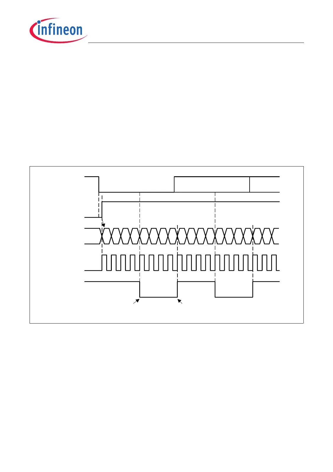
The content of bit field USR.URR determines the operation of an internal sampling
reload counter that is clocked with f
MSC
. Figure 21-18 shows the operation of the
sampling counter at the beginning of an upstream frame with a divide factor DF of 8
(OCSR.URR = 010
B
is equal to DF = 8) which means eight sampling clocks per each
frame bit cell.
When the upstream channel is in idle state it waits for a falling edge (1-to-0 transition) at
SI. Therefore, the sample counter starts counting up and is reset when the selected
divide factor DF shown in Table 21-6 is reached. In the middle of the sampling counter’s
count range, the logic state at SI is evaluated and, in case of a data bit, latched in the
receive buffer’s shift register. With the reload of the sampling counter, the shift register
is shifted by one bit position.
Figure 21-18 Upstream Channel Sampling with URR = 010
B
21.1.3.5 Spike Filter
The upstream channel input line SDI is sampled using a built-in spike filter with
synchronization stage, both clocked with f
MSC
. The spike filter is a chain of flip-flops with
a majority decision logic (2 out of 3). A sampled value that is found at least twice in three
samples is taken as data input value for SI.
1
MCT05812_mod
Start BitSI
Reception
Enabled
BR
Sampling
Counter
D0
Sampling Shifting
0235467
MSC
10235467
D1
2
01

 Loading...