TC1796
Peripheral Units (Vol. 2 of 2)
Micro Link Interface (MLI)
User’s Manual 23-117 V2.0, 2007-07
MLI, V2.0
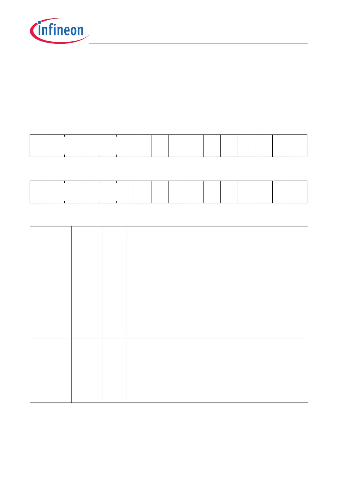
23.4.9 Receiver Interrupt Registers
The Receiver Interrupt Enable Register RIER contains the interrupt enable bits and the
clear bits for all receiver events. The bits marked w are always read as 0.
RIER
Receiver Interrupt Enable Register (A4
H
) Reset Value: 0000 0000
H
31 30 29 28 27 26 25 24 23 22 21 20 19 18 17 16
0
DRA
IR
MPE
IR
PE
IR
ICE
R
CFR
IR3
CFR
IR2
CFR
IR1
CFR
IR0
ME
IR
NFR
IR
r wwwwwwwwww
1514131211109876543210
0
DRA
IE
M
PEIE
PEIE ICE
CFR
IE3
CFR
IE2
CFR
IE1
CFR
IE0
NFR
IE
r rwrwrwrwrwrwrwrw rw
Field Bits Type Description
NFRIE [1:0] rw Normal Frame Received Interrupt Enable
This bit field defines if an SRx output is activated if a
Normal Frame is correctly received.
00
B
The SRx activation is disabled.
01
B
The selected SRx line is activated each time a
Normal Frame is correctly received.
10
B
The selected SRx line is activated each time a
Normal Frame is correctly received that is not
handled automatically by the MLI move engine
(e.g. an Answer Frame).
11
B
Reserved
CFRIEx
(x = 0-3)
2 + x rw Command Received in Pipe x Interrupt Enable
This bit determines if an SRx output is activated if a
Command Frame for pipe x has been received correctly.
0
B
Command received in pipe x event is disabled for
activation of an SRx line.
1
B
Command received in pipe x event is enabled for
activation of an SRx line.

 Loading...