TC1796
System Units (Vol. 1 of 2)
General Purpose I/O Ports and Peripheral I/O Lines
User’s Manual 10-38 V2.0, 2007-07
Ports, V2.0
10.5.3.3 Port 2 Input/Output Control Register 0
Port lines P2.0 and P2.1 are not available. Therefore, the PC0 and PC1 bit fields in
register P2_IOCR0 are not connected to any port lines.
10.5.3.4 Port 2 Input Register
The basic P2_IN register functionality is described on Page 10-17. However, port lines
P2.0 and P2.1 are not available. Therefore, bits P0 and P1 in register P2_IN are always
read as 0.
10.5.3.5 Port 2 Emergency Stop Register
The basic P2_ESR register functionality is described on Page 10-16. At Port 2, only port
lines P2.[15:8] are connected to GPTA I/O lines. Therefore, only these port lines of Port 2
can be controlled for the emergency stop function. The P2_ESR bits EN[7:0] are not
implemented. They are always read as 0 and should be written with 0.
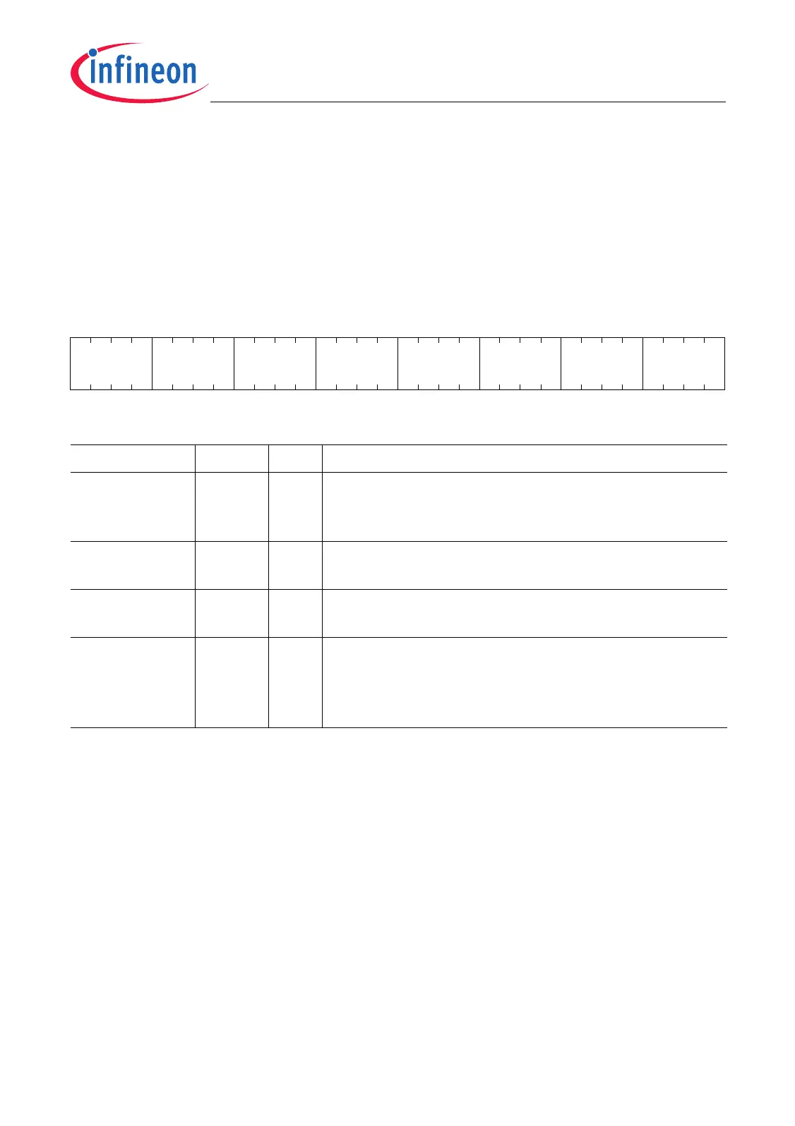
P2_IOCR0
Port 2 Input/Output Control Register 0
(10
H
) Reset Value: 2020 2020
H
31 28 27 24 23 20 19 16 15 12 11 8 7 4 3 0
PC3 0 PC2 0 0010 0 0010 0
rw r rw r rw r rw r
Field Bits Type Description
– [7:4],
[15:12]
rw Reserved
Read as 0010
B
after reset; returns value that was
written.
PC2 [23:20] rw Port Control for Port 2.2
(coding see Table 10-3 on Page 10-10)
PC3 [31:28] rw Port Control for Port 2.3
(coding see Table 10-3 on Page 10-10)
0 [3:0],
[11:8],
[19:16],
[27:24]
r Reserved
Read as 0; should be written with 0.

 Loading...