TC1796
System Units (Vol. 1 of 2)
Introduction
User’s Manual 1-21 V2.0, 2007-07
Intro, V2.0
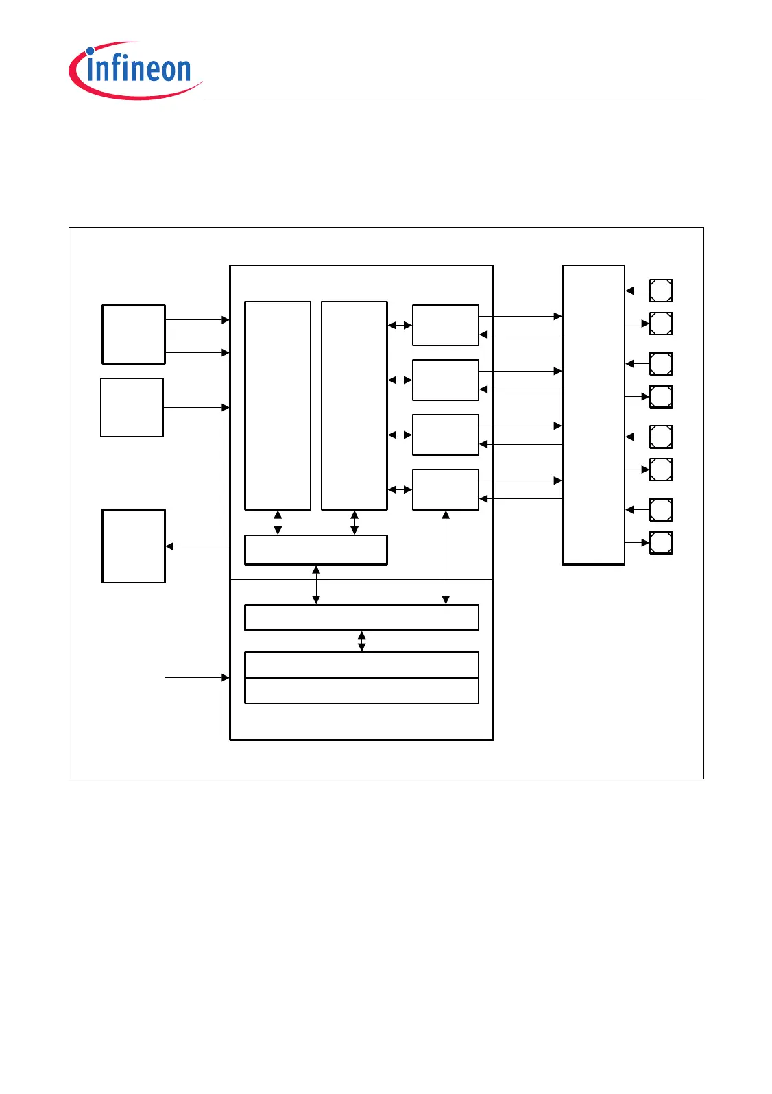
1.3.1.4 MultiCAN Controller
The MultiCAN module contains four independent CAN nodes, representing four serial
communication interfaces.
Figure 1-5 Overview of the MultiCAN Module with Time-Triggered Extension
The MultiCAN module contains four independently operating CAN nodes with Full-CAN
functionality that are able to exchange Data and Remote Frames via a gateway function.
Transmission and reception of CAN frames is handled in accordance with CAN
specification V2.0 B (active). Each CAN node can receive and transmit standard frames
with 11-bit identifiers as well as extended frames with 29-bit identifiers.
All four CAN nodes share a common set of message objects. Each message object can
be individually allocated to one of the CAN nodes. Besides serving as a storage
container for incoming and outgoing frames, message objects can be combined to build
gateways between the CAN nodes or to set up a FIFO buffer.
MultiCAN Module Kernel
MCA05577
Interrupt
Control
f
CAN
Port
Control
CAN
Node 1
CAN Control
Message
Object
Buffer
128
Objects
Timing Control and Synchronization
Scheduler
ScheduleTiming DataMemory
Time-Triggered Extension TTCAN
CAN
Node 0
CAN
Node 2
Linked
List
Control
f
CLC
INT_O
[15:0]
Clock
Control
Address
Decoder
ECTT[7:1]
CAN
Node 3
TXDC3
RXDC3
TXDC2
RXDC2
TXDC1
RXDC1
TXDC0
RXDC0

 Loading...