TC1796
Peripheral Units (Vol. 2 of 2)
Micro Link Interface (MLI)
User’s Manual 23-110 V2.0, 2007-07
MLI, V2.0
23.4.7 Receiver Status/Control Registers
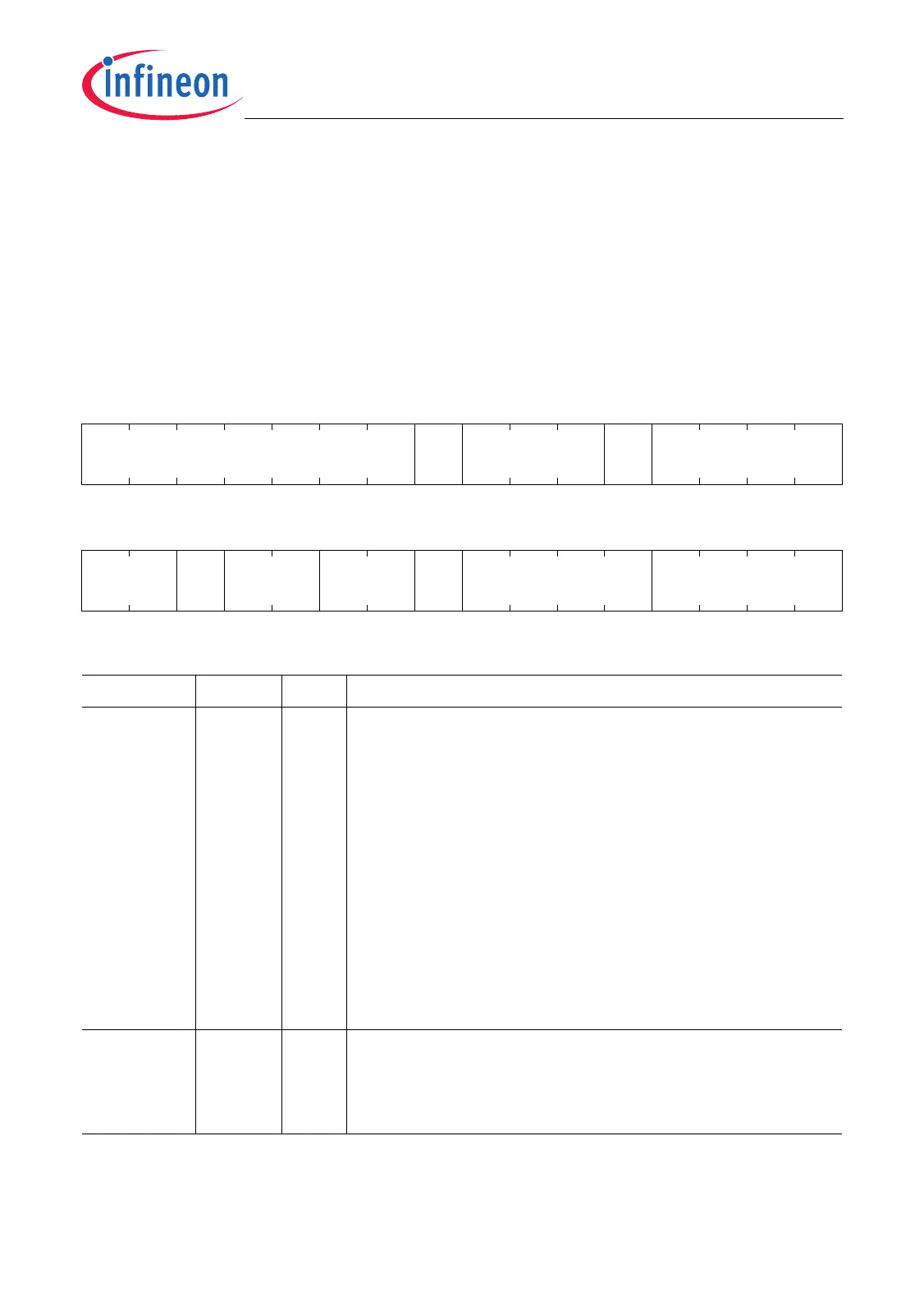
The Receiver Control Register RCR contains control and status bits/bit fields that are
related to the MLI receiver operation.
Bit RCVRST is automatically overwritten after a reset (see Page 23-66) with a value
given in the implementation chapter (see Page 23-127).
RCR
Receiver Control Register (68
H
) Reset Value: 0100 0000
H
31 30 29 28 27 26 25 24 23 22 21 20 19 18 17 16
0
RCV
RST
0BEN MPE
r rw r rw rwh
1514131211109876543210
RPN PE TF DW MOD CMDP3 DPE
rh rh rh rh rh rh rh
Field Bits Type Description
DPE [3:0] rh Delay for Parity Error
DPE determines the number of RCLK clock periods that
the MLI receiver waits before the RREADY signal is
raised again when it has detected a parity error (see
Page 23-22). When a pipe 1 Command Frame is
received by the MLI receiver, the command code is
stored in this bit field (see Page 23-39).
0000
B
Zero RCLK clock period delay is selected.
0001
B
One RCLK clock period delay is selected.
0010
B
Two RCLK clock periods delay is selected.
…
B
…
1110
B
Fourteen RCLK clock periods delay is selected.
1111
B
Fifteen RCLK clock periods delay is selected.
CMDP3 [7:4] rh Command From Pipe 3
When a pipe 3 Command Frame is received by the MLI
receiver, the command code is stored in this bit field.
Pipe 3 commands are free for software use.

 Loading...