TC1796
Peripheral Units (Vol. 2 of 2)
Micro Link Interface (MLI)
User’s Manual 23-90 V2.0, 2007-07
MLI, V2.0
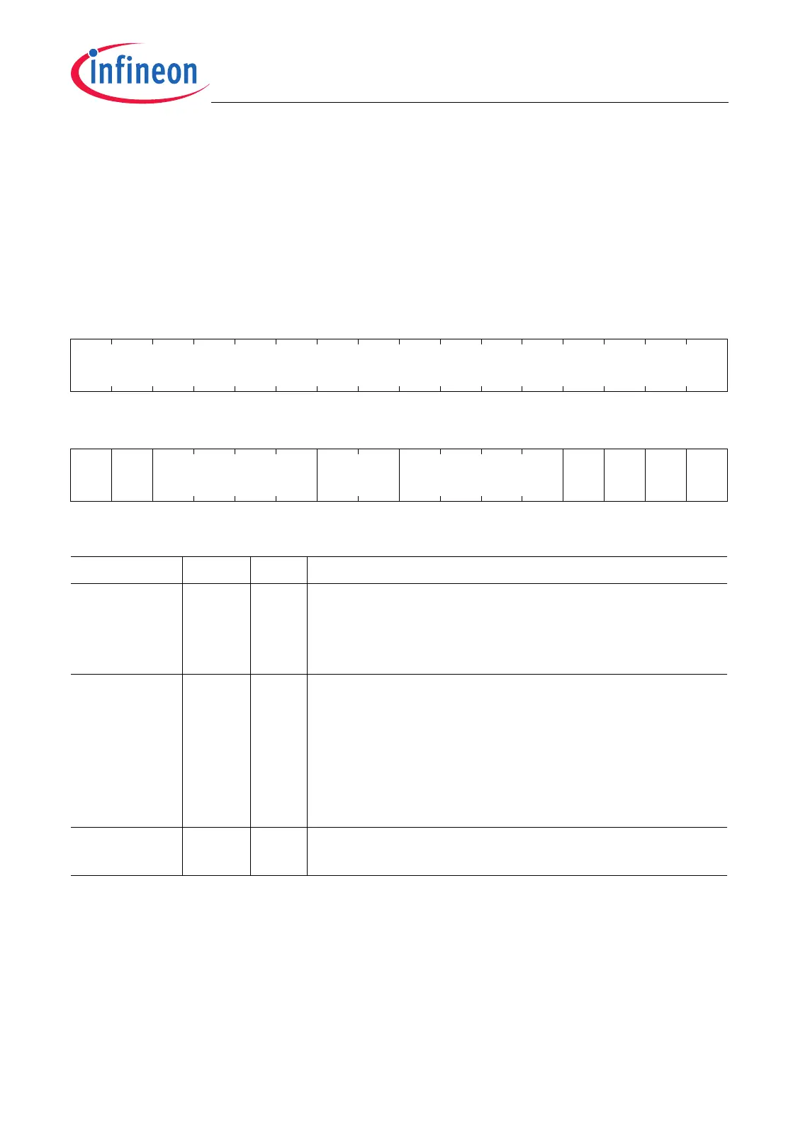
23.4.4 Transmitter Status/Control Registers
The Transmitter Control Register TCR includes transmitter related control bits and bit
fields that are used for parity/acknowledge, address optimization, TDATA idle polarity,
retry, and transmitter enable/disable control.
TCR
Transmitter Control Register (10
H
) Reset Value: 0000 0110
H
31 30 29 28 27 26 25 24 23 22 21 20 19 18 17 16
0
r
1514131211109876543210
TP NO MDP MNAE MPE 0 0 DNT MOD
rw rw rw rwh rwh r rw rw rw
Field Bits Type Description
MOD 0rwMode of Operation
This bit enables the MLI transmitter.
0
B
The MLI transmitter is disabled.
1
B
The MLI transmitter is enabled.
DNT 1rwData in Not Transmission
This bit determines the level of the transmitter data line
TDATA when no transmission is in progress.
0
B
TDATA is at low level if no transmission is
running.
1
B
TDATA is at high level if no transmission is
running.
0 2rwReserved
Read as 0 after reset; must be written with 0.

 Loading...