TC1796
System Units (Vol. 1 of 2)
General Purpose I/O Ports and Peripheral I/O Lines
User’s Manual 10-39 V2.0, 2007-07
Ports, V2.0
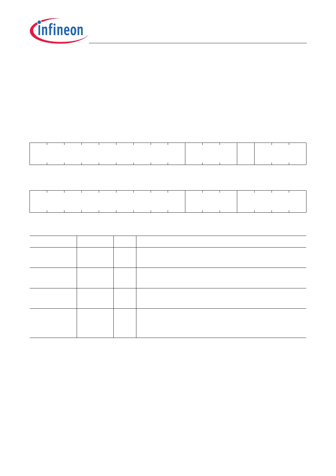
10.5.3.6 Port 2 Pad Driver Mode Register and Pad Classes
The Port 2 pad driver mode register contains four bit fields that determine the pad driver
mode (output driver strength and slew rate) of Port 2 line groups. The Port 2 port lines
are assigned to A1 and A2 pad classes (see also Figure 10-6).
P2_PDR
Port 2 Pad Driver Mode Register (40
H
) Reset Value: 0000 0000
H
31 30 29 28 27 26 25 24 23 22 21 20 19 18 17 16
0 PDSLS1 0 PDSLS0
rrwrrw
1514131211109876543210
0PD10
rrwr
Field Bits Type Description
PD1 [6:4] rw Pad Driver Mode for P2.[15:8]
(Class A1 pads; for coding see Page 10-11)
PDSLS0 [18:16] rw Pad Driver Mode for P2.[3:2]
(Class A2 pads; for coding see Page 10-11)
PDSLS1 [22:20] rw Pad Driver Mode for P2.[7:4]
(Class A2 pads; for coding see Page 10-11)
0 [3:0],
[15:7], 19,
[31:23]
r Reserved
Read as 0; should be written with 0.

 Loading...