TC1796
Peripheral Units (Vol. 2 of 2)
Controller Area Network (MultiCAN) Controller
User’s Manual 22-201 V2.0, 2007-07
MultiCAN, V2.0
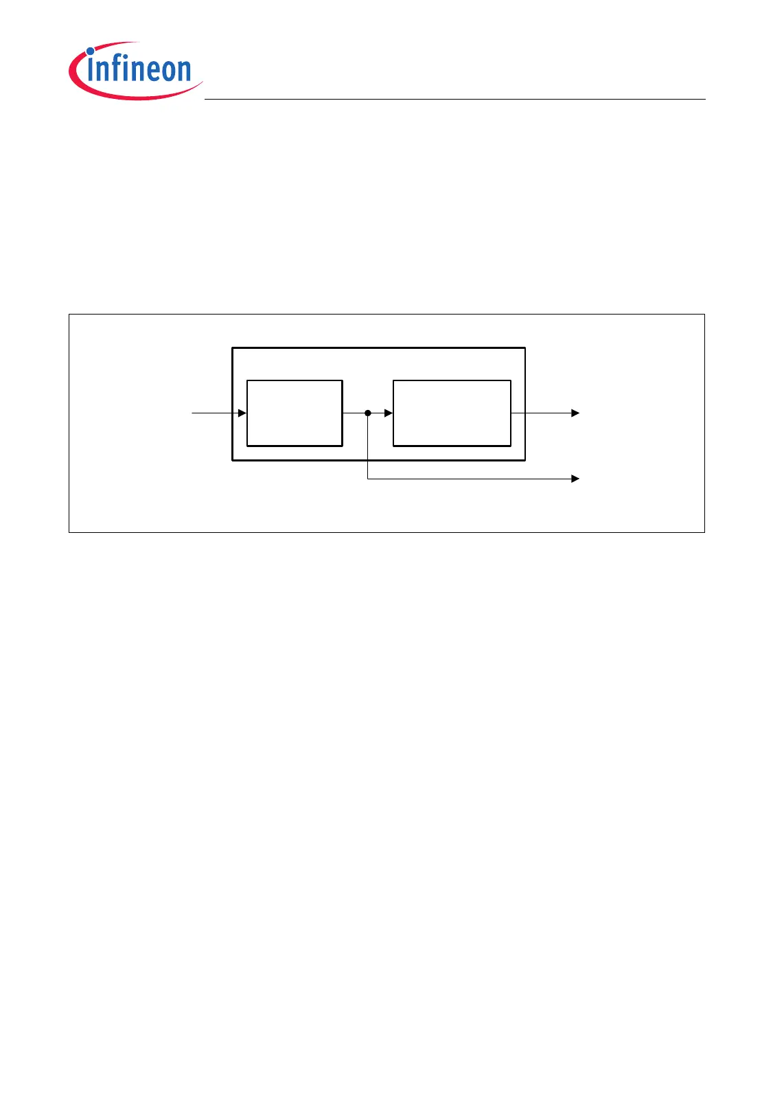
22.9.3 Module Clock Generation
As shown in Figure 22-40, the clock signals for the MultiCAN module are generated and
controlled by a clock control unit. This clock generation unit is responsible for the
enable/disable control, the clock frequency adjustment, and the debug clock control.
This unit includes two registers:
• CAN_CLC: generation of the module control clock f
CLC
• CAN_FDR: frequency control of the module timer clock f
CAN
Figure 22-40 MultiCAN Module Clock Generation
The module control clock f
CLC
is used inside the MultiCAN module for control purposes
such as clocking of control logic and register operations. The frequency of f
CLC
is
identical to the system clock frequency f
SYS
. The clock control register CAN_CLC makes
it possible to enable/disable f
CLC
under certain conditions.
The module timer clock f
CAN
is used inside the MultiCAN module as input clock for all
timing relevant operations (e.g. bit timing). The settings in the CAN_FDR register
determine the frequency of the module timer clock f
CAN
according the following two
formulas:
(22.1)
(22.2)
Equation (22.1) applies to normal divider mode (CAN_FDR.DM = 01
B
) of the fractional
divider. Equation (22.2) applies to fractional divider mode (CAN_FDR.DM = 10
B
).
Note: The CAN module is disabled after reset. In general, after reset, the module control
clock f
CLC
must be switched on (writing to register CAN_CLC) before the
frequency of the module timer clock f
CAN
is defined (writing to register CAN_FDR).
MCA05866
Clock Control
Register
CAN_CLC
f
CLC
MultiCAN Clock Control
f
CAN
f
SYS
Fractional Divider
Register
CAN_FDR
f
CAN
f
SYS
1
n
---
× with n = 1024 - CAN_FDR.STEP =
f
CAN
f
SYS
n
1024
-------------
× with n = 0-1023 =

 Loading...