TC1796
Peripheral Units (Vol. 2 of 2)
Fast Analog-to-Digital Converter (FADC)
User’s Manual 26-11 V2.0, 2007-07
FADC, V2.0
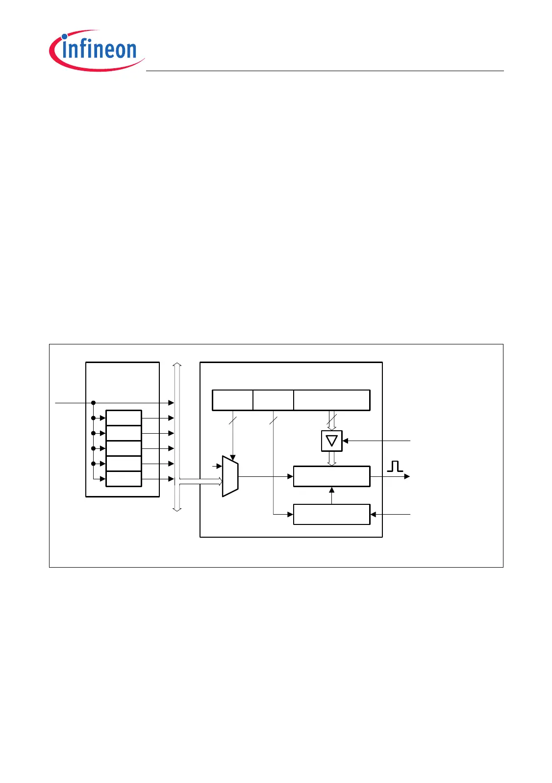
26.1.4 Channel Timer
Each of the FADC channels contains an 8-bit Channel Timer that can be used to
generate periodic conversion requests. The Channel Timer is built up by a decrementing
counter that is reloaded with a programmable value. When the Channel Timer reaches
zero while running, a Channel Timer trigger event is generated and the Channel Timer
is reloaded with the reload value CFGRx.CTREL when the requested conversion is
started. With the start of the A/D conversion, request flag CRSR.CRFx is also cleared.
Note that the request flag is set by a timer trigger event only if the gating condition is met
(signal ECHTIMx in Figure 26-4 set).
A clock divider, fed by the module clock f
FADC
and common for all Channel Timers,
generates several clock signals with different periods. Bit field CFGRx.CTF selects
whether or not the channel x timer clock f
CTx
is enabled and, if enabled, the frequency of
channel x timer input clock f
CTx
.
While the Channel Timer is disabled (CFGRx.CTM = 00
B
) or if the gating condition is not
met (gating line ECHTIMx delivers 0), the channel x timer value is set to 04
H
.
Figure 26-5 Channel Timer Block Diagram
Due to the common divider, the first event at the trigger output of CHTIMx after the start
has a maximum jitter of one clock cycle of the selected channel x timer clock f
CTx
.
A Channel Timer x input clock pulse at f
CTx
is ignored if it occurs in the f
FADC
clock cycle
directly after the Channel x Timer has reached 0. If there is at least one f
FADC
clock cycle
between two Channel x Timer input clock pulses, all Channel x Timer input clock pulses
are taken into account. This leads to a Channel x Timer reload value (CFGRx.CTREL)
whose definition depends on the ratio of f
CLC
/ f
CTx
:
MCB06042
Channel Timer
Channel conversion
started and channel
timer is running
CTF
CFGRx
CTREL
Channel x Timer
trigger event
Channel x Timer
enable ECHTIMx
CTM
8
Run Control
Channel x Timer
To the other three
Channel Timers
÷ 4
÷ 16
÷ 64
÷ 256
÷ 1024
f
FADC
Clock Divider
for
Channel Timers
f
CTx
0
3 2

 Loading...