TC1796
Peripheral Units (Vol. 2 of 2)
Fast Analog-to-Digital Converter (FADC)
User’s Manual 26-58 V2.0, 2007-07
FADC, V2.0
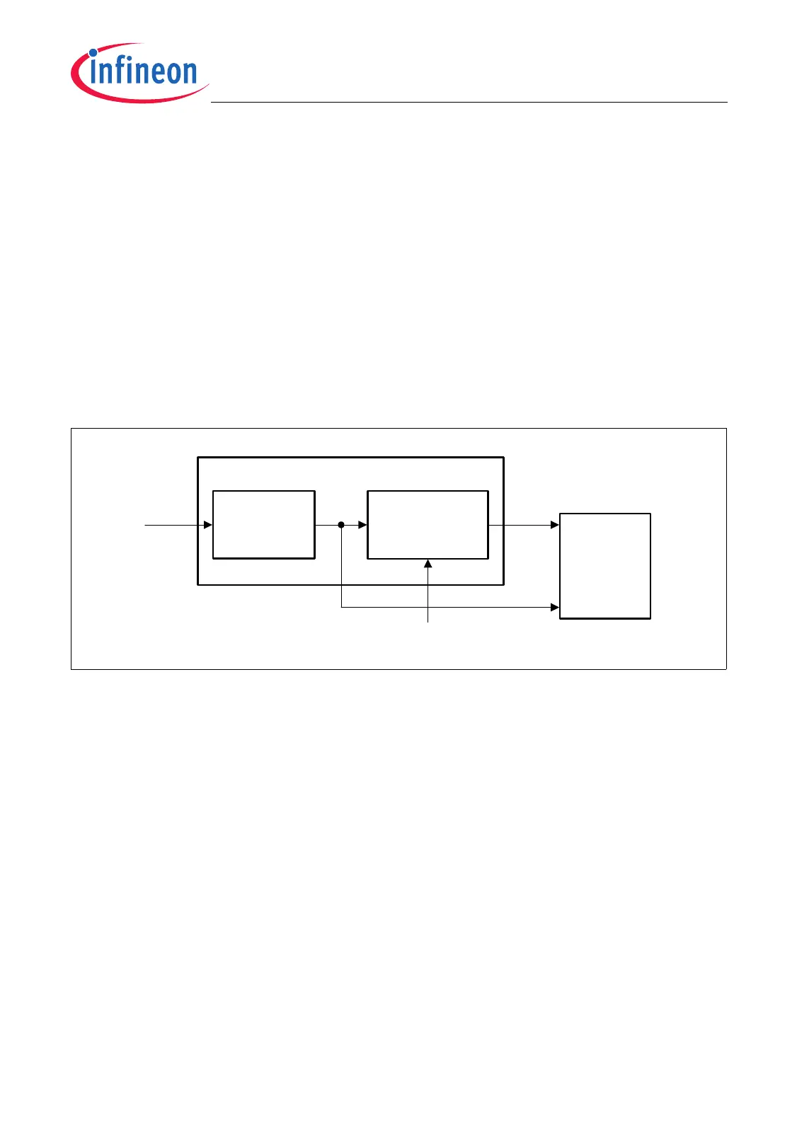
26.3.3 Clock Control
The FADC module is provided with two clock signals:
• f
CLC
This is the module clock that is used inside the FADC kernel for control purposes
such as clocking of control logic and register operations. The frequency of f
CLC
is
always identical to the system clock frequency f
SYS
. The clock control register
FADC_CLC makes it possible to enable/disable
f
CLC
under certain conditions.
•
f
FADC
This clock is the module clock that is used in the FADC as the clock for the Channel
Timer and the analog part. It also controls the conversion timing (see Page 26-8).
The fractional divider registers FADC_FDR controls the frequency of f
FADC
and allows
it to be enabled/disabled independently of f
CLC
.
Figure 26-18 FADC Clock Generation
The following formulas define the frequency of f
FADC
:
(26.3)
(26.4)
Equation (26.3) is valid for FADC_FDR.DM = 01
B
(normal divider mode).
Equation (26.4) is valid for FADC_FDR.DM = 10
B
(fractional divider mode).
MCA06055
Clock Control
Register
FADC_CLC
f
CLC
FADC Clock Generation
f
FADC
f
SYS
Fractional Divider
Register
FADC_FDR
ECEN
V
SS
FADC
Module
Kernel
f
FADC
f
SYS
1
n
---
× with n = 1024 - FDR.STEP =
f
FADC
f
SYS
n
1024
-------------
× with n = 0-1023 =

 Loading...