TC1796
System Units (Vol. 1 of 2)
Reset and Boot Operation
User’s Manual 4-3 V2.0, 2007-07
Reset, V2.0
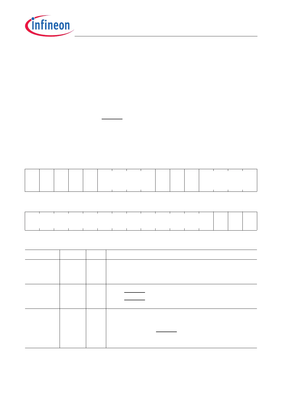
4.1.1 Reset Status and Control Registers
The Reset Status Register RST_SR indicates the cause of a reset and the selected boot
configuration. The Reset Request Register RST_REQ is used to cause a software reset.
4.1.1.1 Reset Status Register
After a reset, the reset status register RST_SR indicates the type of reset which has
occurred and which parts of the TC1796 were affected by the last reset operation.
RST_SR also holds the state of the boot configuration pins HWCFG[3:0] (Port 10) that
have been sampled with the HDRST inactive (low-to-high) transition. Register RST_SR
is a read-only register.
RST_SR
Reset Status Register (F0000014
H
) Reset Values: see Table 4-1
31 30 29 28 27 26 25 24 23 22 21 20 19 18 17 16
0
WDT
RST
SFT
RST
HD
RST
PWO
RST
0
TMP
LS
HW
BRK
IN
0HWCFG
r rhrhrhrh r rhrh r rh
1514131211109876543210
0
RS
EXT
0
RS
STM
rrhrrh
Field Bits Type Description
RSSTM 0rhSystem Timer Reset Status
0
B
The system timer was not reset.
1
B
The system timer was reset.
RSEXT 2rhHDRST Input State during Last Reset
0
B
HDRST was not activated.
1
B
HDRST was activated.
HWCFG [19:16] rh Boot Configuration Selection Status
This bit field indicates the status of the configuration
pins HWCFG[3:0] at Port 10 that has been latched at
the rising edge of HDRST. HWCFG[3:0] is assigned to
P10.[3:0].

 Loading...