TC1796
System Units (Vol. 1 of 2)
Reset and Boot Operation
User’s Manual 4-4 V2.0, 2007-07
Reset, V2.0
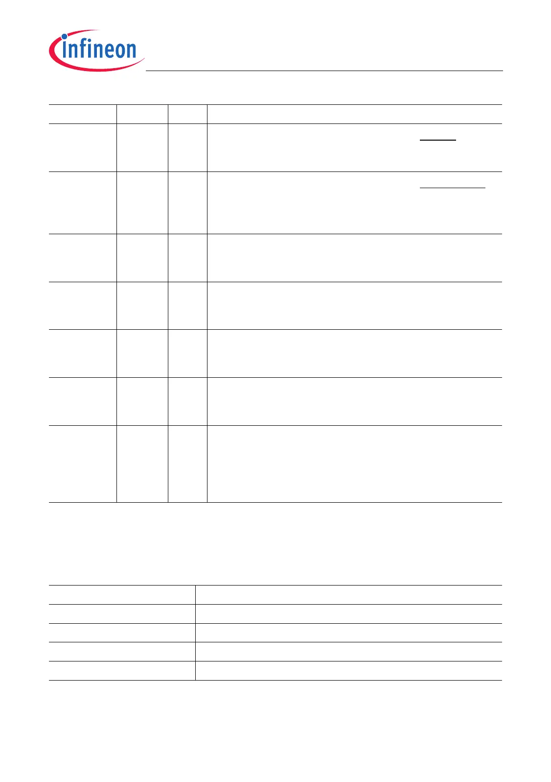
Table 4-1 defines the reset values of the RST_SR register depending on the reset
source.
HWBRKIN 21 rh Latched State of BRKIN Input
This bit indicates the logical state of the BRKIN input
that has been latched at the end of a power-on reset.
TMPLS 22 rh Latched State of TESTMODE Input
This bit indicates the logical state of the TESTMODE
input pin that has been latched at the end of a power-on
reset.
PWORST 27 rh Power-On Reset Status Flag
0
B
The last reset was not a power-on reset.
1
B
The last reset was a power-on reset.
HDRST 28 rh Hardware Reset Status Flag
0
B
The last reset was not a hardware reset.
1
B
The last reset was a hardware reset.
SFTRST 29 rh Software Reset Status Flag
0
B
The last reset was not a software reset.
1
B
The last reset was a software reset.
WDTRST 30 rh Watchdog Reset Status Flag
0
B
The last reset was not a watchdog reset.
1
B
The last reset was a watchdog reset.
0 1,
[15:3],
20,
[26:23],
31
r Reserved
Read as 0.
Table 4-1 Reset Values of Register RST_SR
Reset Source Reset Values
Power-on Reset 0000 1000 0XX0 XXXX 0000 0000 0000 0101
B
Hardware Reset 0001 0000 0XX0 XXXX 0000 0000 0000 0000
B
Software Reset 0010 0000 0XX0 XXXX 0000 0000 0000 0X0X
B
Watchdog Timer Reset 0100 0000 0XX0 XXXX 0000 0000 0000 0101
B
Field Bits Type Description

 Loading...