TC1796
Peripheral Units (Vol. 2 of 2)
Analog-to-Digital Converter (ADC)
User’s Manual 25-120 V2.0, 2007-07
ADC, V2.0
25.3.6.4 Service Request Control Registers
Each of the four interrupt request nodes of ADC0 and ADC1 is controlled by a service
request control register.
Note: Additional information about service request nodes and the service request control
registers are described on Page 14-3 of the TC1796 User’s Manual System Units
part (Volume 1).
25.3.6.5 Die Temperature Sensor
AIN31of ADC1 is connected to the output of an on-chip die temperature measurement
sensor (see also Page 25-101). Detailed information about this die temperature sensor
is provided in the section “Die Temperature Sensor” on Page 5-48 of the TC1796
User’s Manual System Unit (Volume 1).
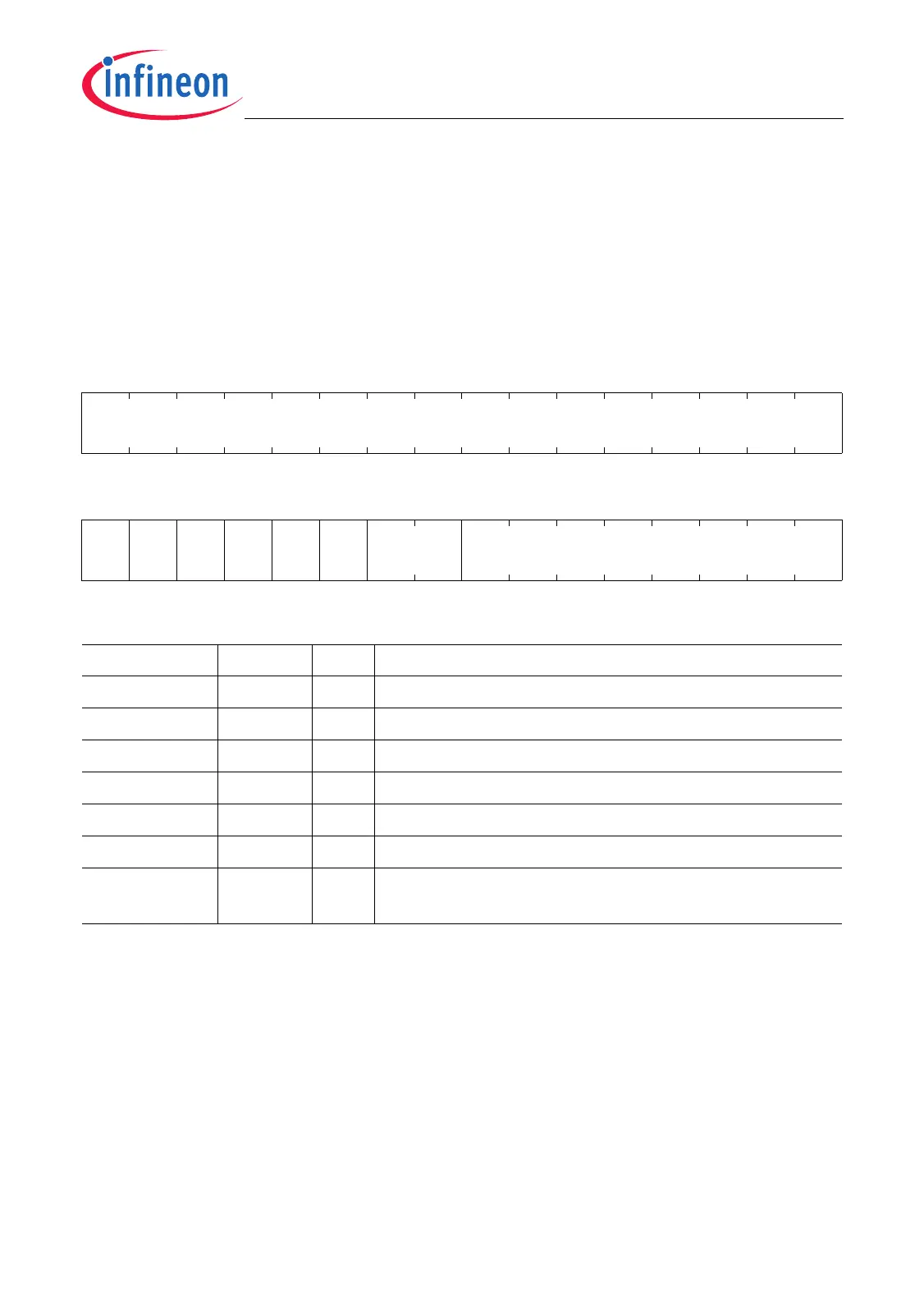
SRCm (m = 0-3)
Service Request Control Register m
(1FC
H
-m*4) Reset Value: 0000 0000
H
31 30 29 28 27 26 25 24 23 22 21 20 19 18 17 16
0
r
1514131211109876543210
SET
R
CLR
R
SRR SRE 0 TOS 0 SRPN
w w rh rw r rw r rw
Field Bits Type Description
SRPN [7:0] rw Service Request Priority Number
TOS 10 rw Type of Service Control
SRE 12 rw Service Request Enable
SRR 13 rh Service Request Flag
CLRR 14 w Request Clear Bit
SETR 15 w Request Set Bit
0 [9:8], 11,
[31:16]
r Reserved
Read as 0; should be written with 0.

 Loading...