TC1796
System Units (Vol. 1 of 2)
Peripheral Control Processor (PCP)
User’s Manual 11-108 V2.0, 2007-07
PCP, V2.0
11.11.40 Instruction Timing
This section gives some information about the duration of PCP instructions. Please note
that there are various conditions that can further affect the duration of PCP instructions
(e.g. external FPI accesses from another FPI Bus master to the PCP memories stall the
PCP Processor Core).
Note: The clock cycles listed in Table 11-15 are PCP module clock cycles. In the
TC1796, the PCP is connected to the System Peripheral Bus (which is a FPI Bus)
and clocked with f
SYS
as module clock (f
SYSmax
= 75 MHz, resulting in a minimum
clock cycle time of 13.3 ns).
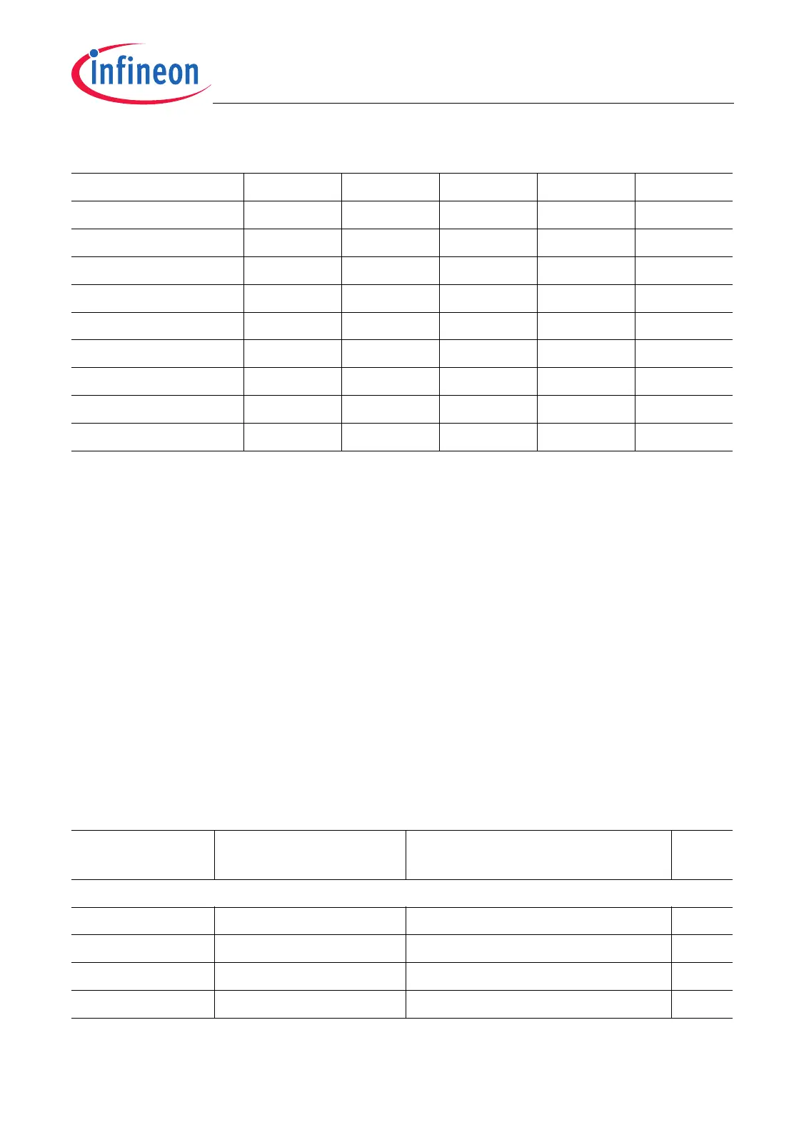
RR –––yesyes
RL – – yes yes yes
SET –––––
SHR –––yes
3)
yes
SHL – – yes yes yes
ST –––––
SUB – yes yes yes yes
XCH –––yesyes
XOR –––yesyes
1) CN1Z is only modified by the BCOPY, COPY or EXIT instructions if the instruction has been configured to
decrement R6.CNT1 (for BCOPY/COPY CNC = 1 or CNC = 2, for EXIT EC = 1). All other instructions have
no effect on the CN1Z flag.
2) For the LD.I type of instruction, flag N is always cleared, as bit 31 of the result is always 0.
3) Flag N is always cleared, as bit 31 of the result is always 0.
Table 11-15 Instruction Timing
Instruction Number of Clock
Cycles
Comments Notes
Control
NOP 1 – –
COPY – –
1)
EXIT f = 9, s = 7, m = 6 –
2)
BCOPY – –
1)
Table 11-14 Flag Updates (cont’d)
Instruction CN1Z V C N Z

 Loading...