TC1796
Peripheral Units (Vol. 2 of 2)
Micro Second Channel (MSC)
User’s Manual 21-70 V2.0, 2007-07
MSC, V2.0
21.3.4 Port Control
MSC0 and MSC1 clock and data output lines are connected to dedicated differential
output drivers. Some of the MSC module I/O lines are connected to I/O ports and
therefore controlled in the port logic (see also Figure 21-29). The following port control
operations selections must be executed for these I/O lines:
• Input/output function selection (IOCR registers)
• Pad driver characteristics selection for the outputs (PDR registers)
21.3.4.1 Input/Output Function Selection
The port input/output control registers contain the bit fields that select the digital output
and input driver characteristics such as port direction (input/output) with alternate output
selection, pull-up/down devices, and open-drain selections. The I/O lines for the MSC
modules are controlled by the Port 5 and Port 9 input/output control registers.
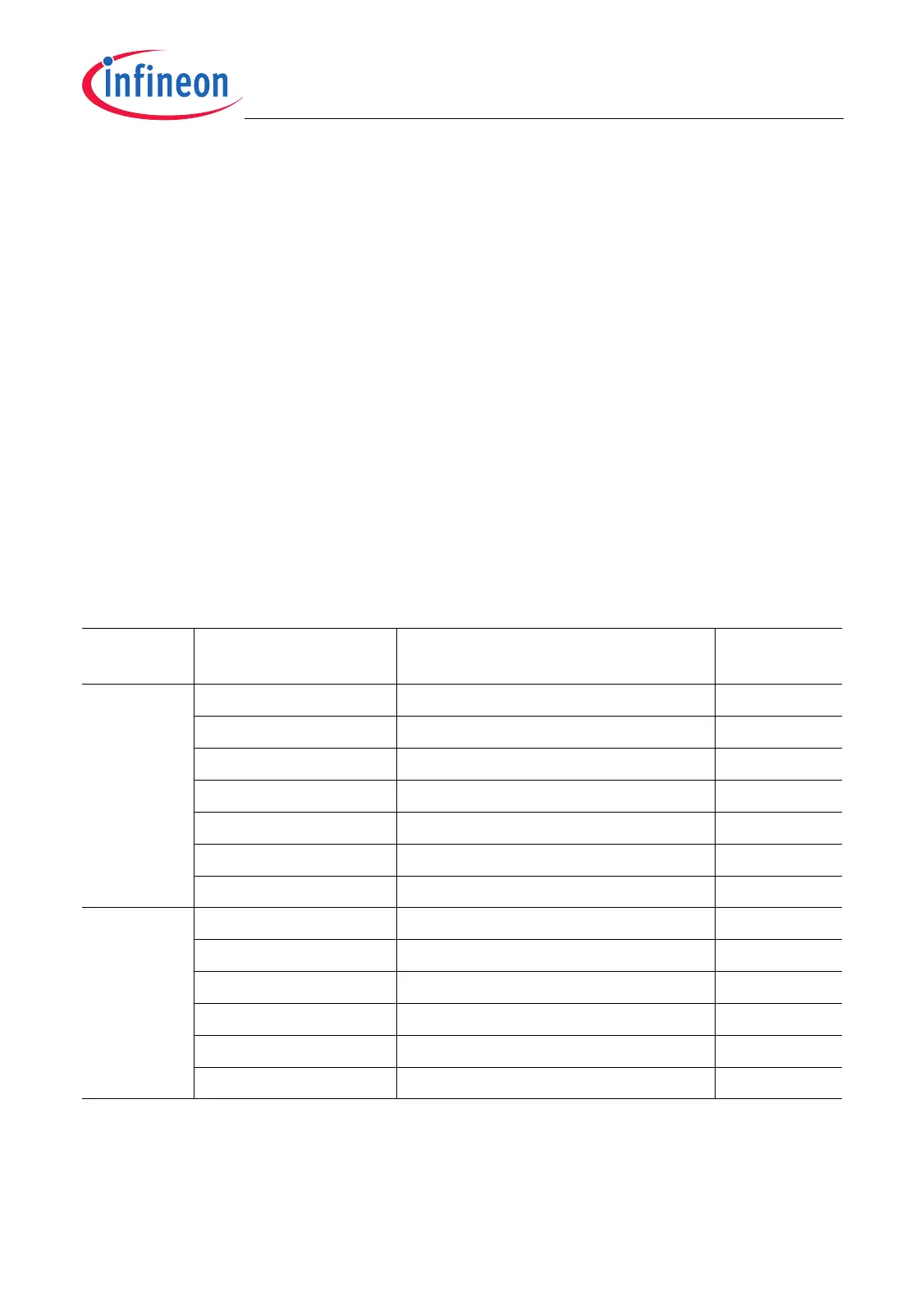
Table 21-10 shows in an overview how bits and bit fields must be programmed for the
required I/O functionality of the MSC I/O lines.
Table 21-10 MSC0 and MSC1 I/O Line Selection and Setup
Module Port Lines Input/Output Control
Register Bits
1)
1) Possible Px bit field combinations see Table 21-11.
I/O
MSC0 P5.4 / EN00 P5_IOCR4.PC4 = 1X11
B
Output
P5.5 / SDI0
2)
2) For the upstream channel serial data inputs, additionally bit fields MSC0_OCR.SDISEL (for SDI0) and
MSC1_OCR.SDISEL (for MSC1) must be set to 000
B
.
P5_IOCR4.PC5 = 0XXX
B
Input
P9.4 / EN03 P9_IOCR4.PC4 = 1X11
B
Output
P9.5 / EN02 P9_IOCR4.PC5 = 1X11
B
Output
P9.6 / EN01 P9_IOCR4.PC6 = 1X11
B
Output
P9.7 / SOP0B P9_IOCR4.PC7 = 1X11
B
Output
P9.8 / FCLP0B P9_IOCR8.PC8 = 1X11
B
Output
MSC1
3)
3) Chip enable output 3 (EN3) of the MSC1 module is not connected in the TC1796.
P5.6 / EN10 P5_IOCR4.PC6 = 1X11
B
Output
P5.7 / SDI1
2)
P5_IOCR4.PC7 = 0XXX
B
Input
P9.0 / EN12 P9_IOCR8.PC0 = 1X11
B
Output
P9.1 / EN11 P9_IOCR8.PC1 = 1X11
B
Output
P9.2 / SOP1B P9_IOCR8.PC2 = 1X11
B
Output
P9.3 / FCLP1B P9_IOCR8.PC3 = 1X11
B
Output

 Loading...