TC1796
Peripheral Units (Vol. 2 of 2)
Micro Link Interface (MLI)
User’s Manual 23-49 V2.0, 2007-07
MLI, V2.0
23.2.3 Interface Description
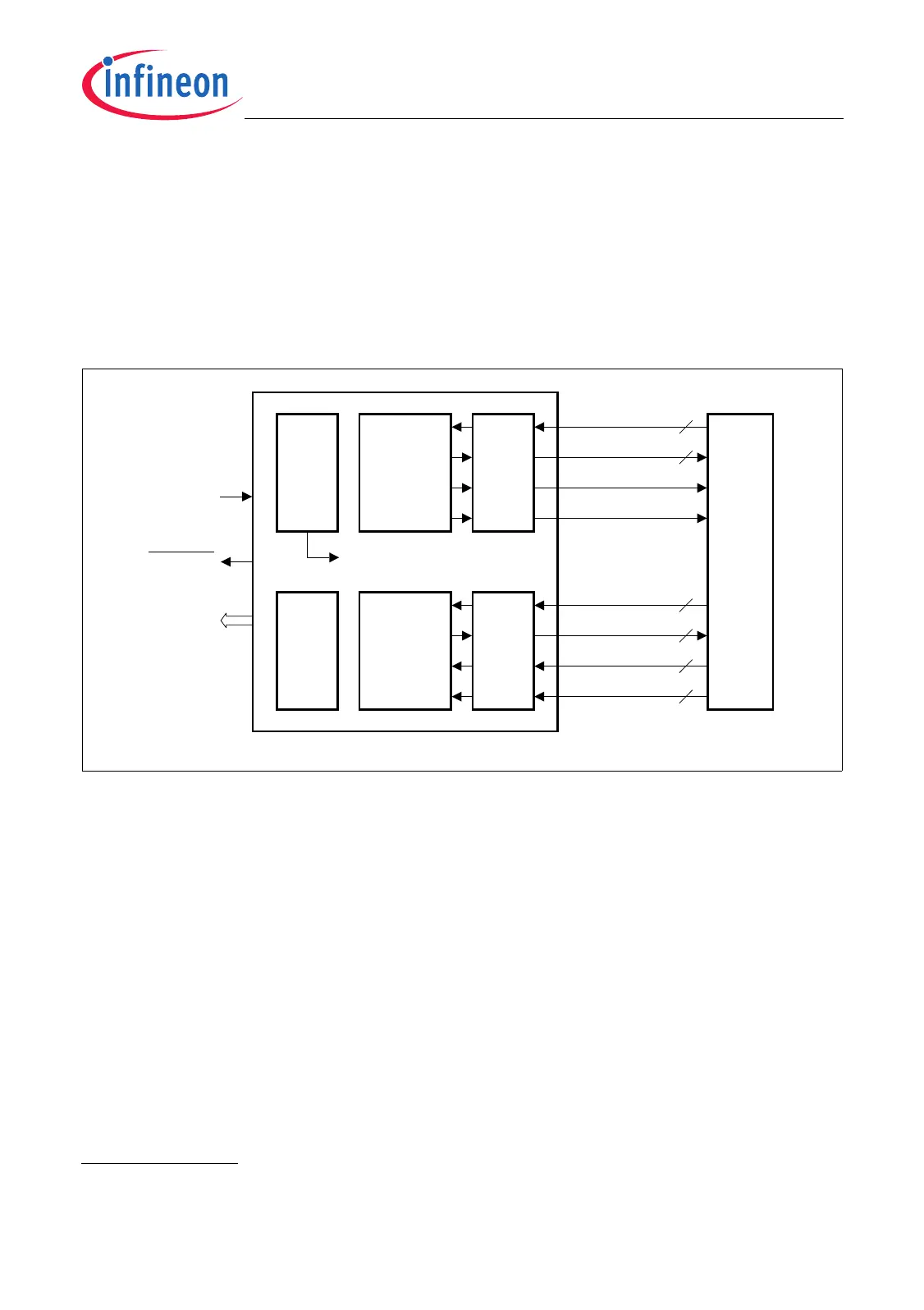
The MLI transmitter and MLI receiver communicate with other MLI receivers and MLI
transmitters via a four-line serial connection each. Several I/O lines of these connections
are available outside the MLI module kernel as a four-line output or input vector with
index numbering A, B, C and D. The MLI module internal I/O control blocks define which
signal of a vector is actually taken into account and also allow polarity inversions (to
adapt to different physical interconnection means).
Figure 23-34 General Block Diagram of the MLI Module
Each input/output signal used for MLI communication between a transmitter and a
receiver can be disabled and inverted in its polarity. Please note that all waveform
diagrams in the MLI chapter refer to non-inverted signals. If polarity inversions are
programmed, the waveform diagrams have to be interpreted accordingly. In order to
avoid naming mismatches, the signals keep their names, although a polarity inversion
might have been programmed. If desired, polarity inversions for the same signal have to
be programmed in the transmitter and in the receiver to guaranty signal consistency
(there has always to be an even number of inversions between an MLI transmitter and
receiver). After reset, the following setting is applied, allowing MLI communication
without modification of register OICR
1)
:
• The signal with the index A is selected from each input/output vector.
• TCLK generation is enabled and RCLK reception is enabled.
• Polarity inversion is disabled for all signals (no inversion).
1) Other services (e.g. an automatic boot sequence or a boot routine) can change the OICR setting. Differing
values are then indicated in the corresponding implementation chapter.
MCB05870_mod
Port
Control
SR[7:0]
TREA DY[D :A ]
TVALID[D:A]
RCLK[D:A]
TDATA
TCLK
RREADY[D:A]
RVALID[D:A]
RDA TA[D:A]
Fract .
Divider
Move
Engine
f
MLI
BRKOUT
MLI
Transmitter
MLI
Receiver
MLI Module
I/O
Control
I/O
Control
4
4
4
4
4
4
f
SYS
 Loading...