TC1796
Peripheral Units (Vol. 2 of 2)
Micro Second Channel (MSC)
User’s Manual 21-22 V2.0, 2007-07
MSC, V2.0
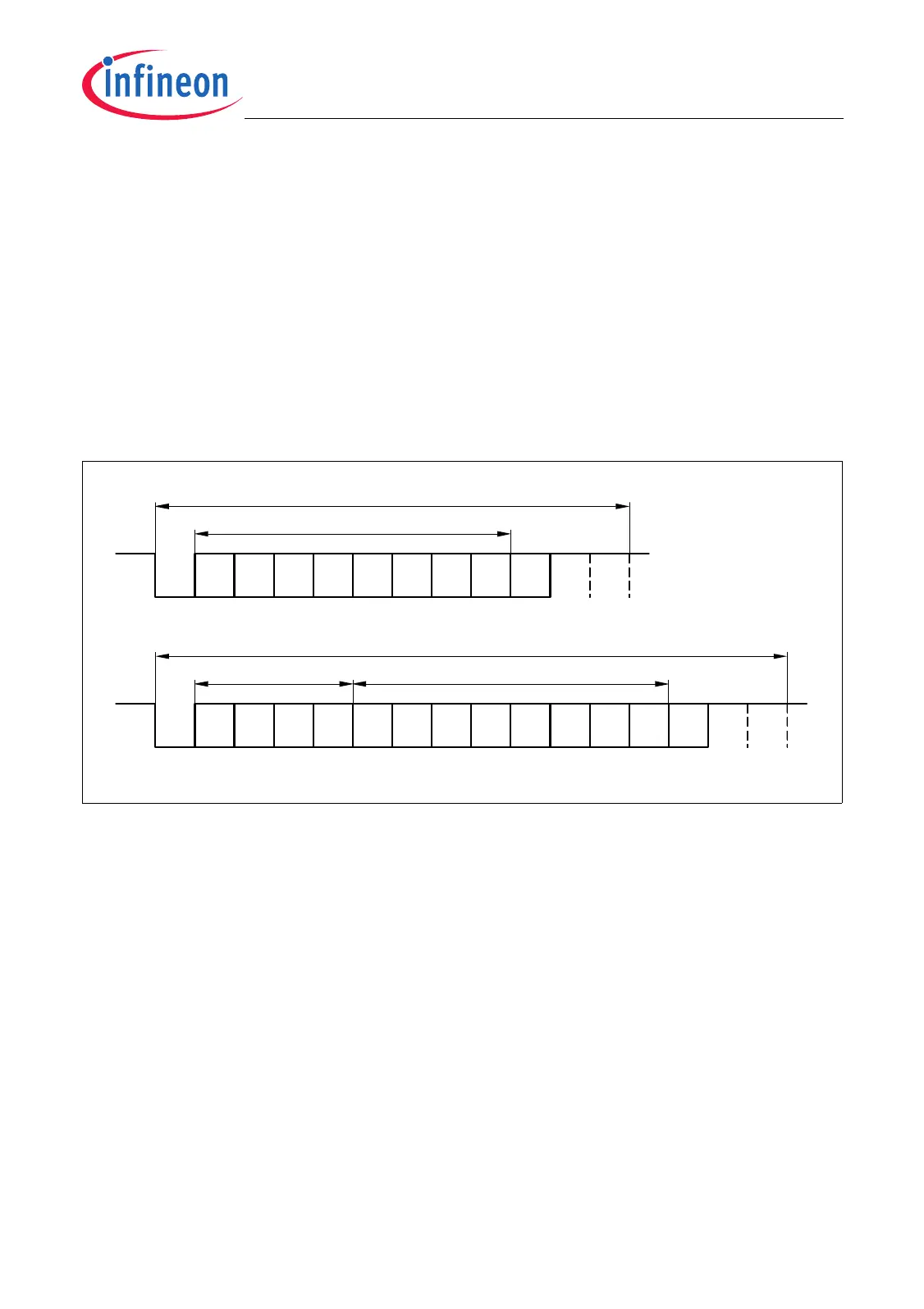
21.1.3.1 Data Frames
The asynchronous data frames used by the upstream channel include four basic parts:
1. One start bit, always at low level
2. An 8-bit data field D[7:0] with LSB first
3. An optional 4-bit address field A[3:0] with LSB first
4. One parity bit and two stop bits, that are always at high level
As shown in Figure 21-15, the 16-bit upstream data frame includes an additional 4-bit
address field. The upstream frame type is selected by bit USR.UFT.
• USR.UFT = 0: 12-bit upstream data frame selected
• USR.UFT = 1: 16-bit upstream data frame with 4-bit address field selected
Figure 21-15 Upstream Channel Frame Types
21.1.3.2 Parity Checking
The incoming parity bit of the data frames can be checked by the upstream channel.
When a parity error is detected, the parity error flag PERR in the related Upstream Data
Register UDx is set. Note that a setting of the parity error flag PERR does not generate
an interrupt. The PERR bits must be checked by software. Further, the UDx registers
store the parity bit of the incoming data frame (UDx.P) and the parity bit that is generated
internally (UDx.IPF).
Bit USR.PCTR determines the parity mode, even or odd, that is selected for parity
checking. With USR.PCTR = 0, even parity mode is selected. Even parity means that the
parity bit is set on an odd number of 1s in the data field (12-bit upstream data frame) or
in the address plus data field (16-bit upstream data frame). With USR.PCTR = 1, odd
parity mode is selected. In odd parity mode, the parity bit is set on an even number of 1s
of the related data.
MCT05809
D5
D0
LSB
D3D1 D2 D4
D7
MSB
D6
Start
Bit
Parity
Bit
Stop
Bit
Stop
Bit
12-Bit Upstream Data Frame
D5
D0
LSB
D3D1 D2 D4
D7
MSB
D6
Start
Bit
Parity
Bit
Stop
Bit
Stop
Bit
8-Bit Data Field
16-Bit Upstream Data Frame
A0
LSB
A3
MSB
A1 A2
4-Bit Address Field
8-Bit Data Field

 Loading...