TC1796
Peripheral Units (Vol. 2 of 2)
Asynchronous/Synchronous Serial Interface (ASC)
User’s Manual 19-36 V2.0, 2007-07
ASC, V2.0
19.3.2.3 Port Control Registers
As shown in Figure 19-14, the I/O lines of the ASC modules are connected to Class A2
port pins of Port 5 and Port 6. Additionally to the PISEL register programming, the
required ASC port lines must be programmed by software for the desired ASC
input/output functionality. Two selections must be executed:
• Input/output function selection
(controlled by the port input/output control registers IOCR)
• Pad driver characteristics selection for the outputs
(controlled by the port pad driver mode register PDR)
Input/Output Function Selection
The port input/output control registers contain the 4-bit wide bit fields that select the
digital output and input driver characteristics such as pull-up/down devices, port direction
(input/output), open-drain, and alternate output selections individually for each pin. The
I/O lines for the ASC modules are controlled by the port input/output control registers
P5_IOCR0 and P6_IOCR8.
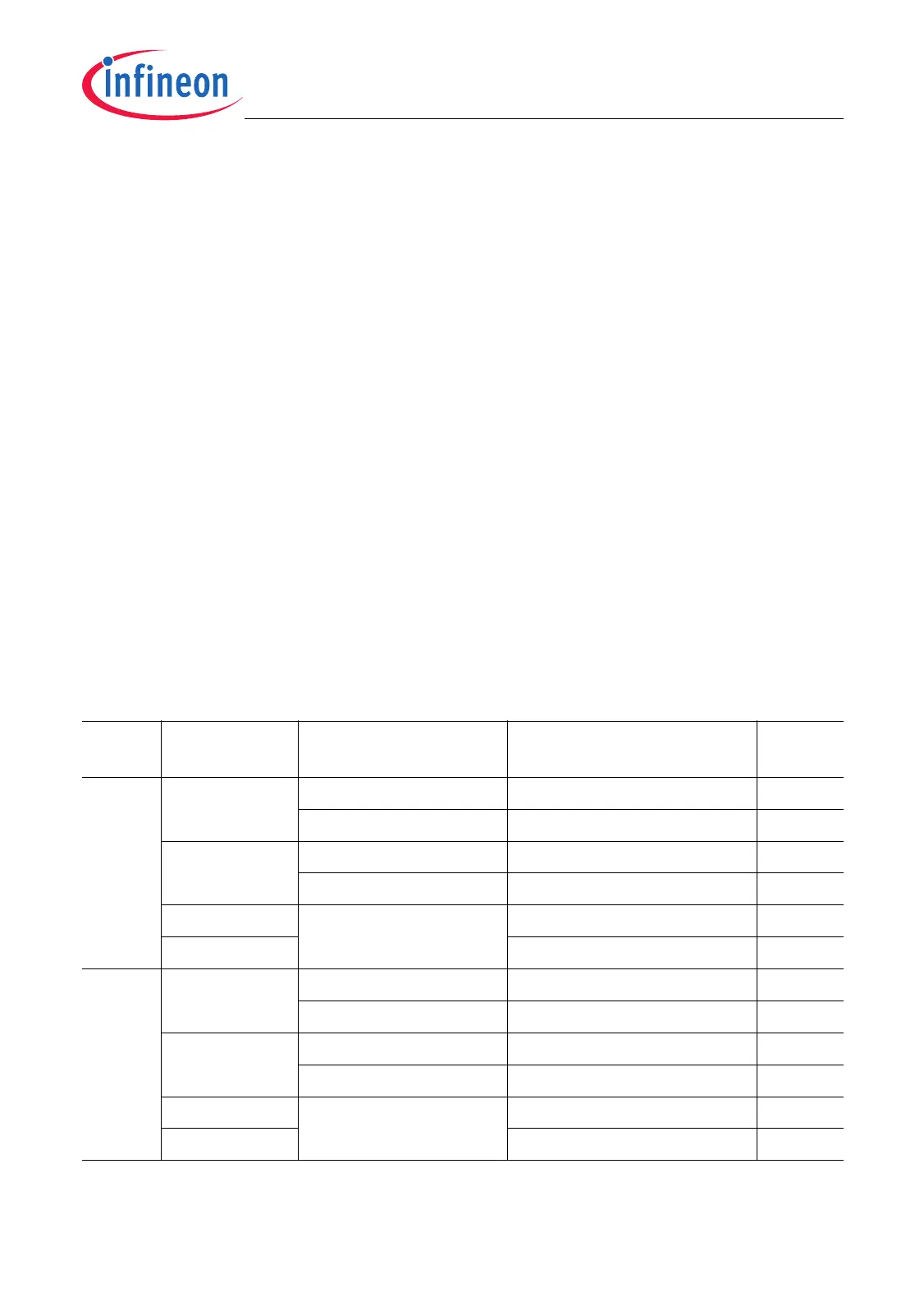
Table 19-8 shows how bits and bit fields must be programmed for the required I/O
functionality of the ASC I/O lines. This table also shows the values of the peripheral input
select registers.
Table 19-8 ASC0/ASC1 I/O Control Selection and Setup
Module Port Lines PISEL Register Input/Output Control
Register Bits
1)
1) Valid PCx bit field combinations see Table 19-9.
I/O
ASC0 P5.0/RXD0A ASC0_PISEL.RIS = 0 P5_IOCR0.PC0 = 0XXX
B
Input
– P5_IOCR0.PC0 = 1X01
B
Output
2)
2) Applicable in Synchronous Mode only.
P6.8/RXD0B ASC0_PISEL.RIS = 1 P6_IOCR8.PC8 = 0XXX
B
Input
– P6_IOCR8.PC8 = 1X10
B
Output
2)
P5.1/TXD0A – P5_IOCR0.PC1 = 1X01
B
Output
P6.9/TXD0B P6_IOCR8.PC9 = 1X10
B
Output
ASC1 P5.2/RXD1A ASC1_PISEL.RIS = 0 P5_IOCR0.PC2 = 0XXX
B
Input
– P5_IOCR0.PC2 = 1X01
B
Output
2)
P6.10/RXD1B ASC1_PISEL.RIS = 1 P6_IOCR8.PC10 = 0XXX
B
Input
– P6_IOCR8.PC10 = 1X10
B
Output
2)
P5.3/TXD1A – P5_IOCR0.PC3 = 1X01
B
Output
P6.11/TXD1B P6_IOCR8.PC11 = 1X10
B
Output

 Loading...